
Native multicast
SD-Access forwards multicast two ways. Head-end replication uses the overlay: the first-hop router, an edge or border node, copies each packet into unicast VXLAN for every node with receivers. Native multicast uses the underlay: traffic is encapsulated into an underlay multicast group and the underlay replicates it, which needs multicast on every device between the first and last hops.
By Arif, founder of Daveth · Updated
The full 9 min walkthrough is in Daveth Pro (Network). See what the plan opens
What this page answers
What is SD-Access head-end replication?
Overlay multicast where the first-hop router, an edge node for a source inside the fabric or a border node for one outside, replicates each packet and sends the copies in unicast IP headers to the fabric devices with receivers. Read it in “Head-end replication”
What is the difference between head-end replication and native multicast?
Head-end replication copies at the ingress node and sends unicast. Native multicast encapsulates the traffic into another multicast group and lets the whole underlay replicate it, so it needs underlay multicast but saves the ingress the work. Read it in “Native multicast”
Two transports, chosen per network
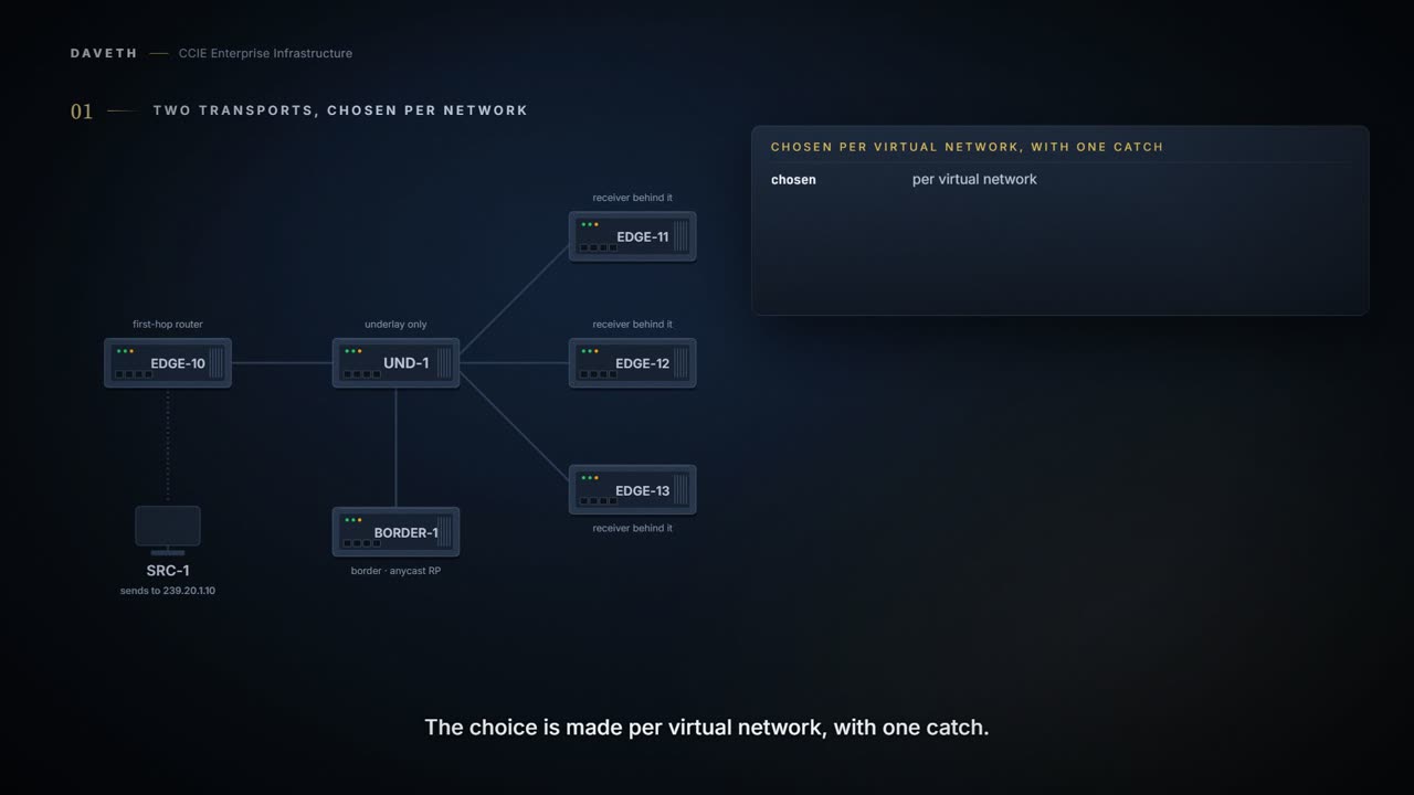
A source sits behind EDGE-10. Receivers sit behind three other edge nodes. The fabric has to get one multicast stream to all three, and there are two ways it can. Who makes the copies?
SD-Access supports two different transport methods for forwarding multicast. One uses the overlay and is referred to as head-end replication, and the other uses the underlay and is called native multicast.
Look at what each one uses. One transport uses the overlay and the other uses the underlay, and everything else on this page follows from which.
And the choice is made per virtual network, with one catch:
Multicast forwarding is enabled per virtual network. However, if native multicast is enabled for a VN, head-end replication cannot be used for another VN in the fabric site. These two options are mutually exclusive within the fabric site.
Read the catch carefully. Two networks can both use head-end replication, and two can both use native multicast. What cannot happen is one of each.
Which is on by default? The head-end document provisions its fabric with what it calls the default settings, and the first one listed is the transport:
It is assumed that Cisco Catalyst Center is used to provision the SDA fabric with the default settings: Replication Implementation is Headend Replication
One micro recap from 1.6, because both words appear below. The overlay and the underlay each run a PIM mode, and they are separate choices:
With PIM-ASM, the root of the tree is the RP. With PIM-SSM, the root of the multicast tree is the source itself. PIM Any Source Multicast (PIM-ASM) and PIM Source-Specific Multicast (PIM-SSM) are supported in both the overlay and underlay.
Head-end replication
What does head-end replication put on the wire?
SDA Headend Replication is a form of overlay multicast, which is used to carry multicast traffic between fabric devices, encapsulating multicast traffic into a unicast IP header. Head-end replication (or ingress replication) is performed by the multicast first-hop router (FHR). If the multicast source is within the fabric, the FHR is an edge node. If the multicast source is outside the fabric, the FHR is a border node. With head-end replication the multicast packets from the source are replicated and sent, via unicast, by the FHR to all last-hop routers (LHRs) with interested subscribers.
Notice the second sentence. The copies are made by the first-hop router, and that is a border node, not an edge node, when the source is outside the fabric.
But the receivers joined toward the rendezvous point first. Where does the traffic go before anything cuts over?
Multicast traffic from 10.47.7.2 to 239.1.1.1 is forwarded out 10.47.6.6 (Border-1) via Unicast VXLAN encapsulation. Border-1 de-encapsulates the VXLAN traffic, and re-encapsulate it to Edge-2 (10.47.1.13)
Computed from the state: campus_vn under head-end replication, on the shared tree. No command prints it.
transport           head-end replication, shared tree
sources             1

link                copies  what they are
SRC-1 to EDGE-10    1       multicast frames from the sources
EDGE-10 to UND-1    1       unicast to BORDER-1
UND-1 to BORDER-1   4       1 up to the border, 3 back down as re-encapsulated unicast
UND-1 to EDGE-11    1       unicast
UND-1 to EDGE-12    1       unicast
UND-1 to EDGE-13    1       unicast

FHR replications    1 per packet
branched by         BORDER-1
Look at the UND-1 to BORDER-1 row. One copy up, three back down: the border is doing the replicating at this moment, not EDGE-10.
Once the Last Hop Router (LHR) Edge-2, receives the multicast packet along the (*,G) tree, it attempts to do SPT cutover and send a PIM (S,G) join to Edge-1. The FHR (Edge-1) has (S,G) pointing directly towards Edge-2's RLOC The underlay network routes this packet from Edge-1 to Edge-2 using unicast routing.
Computed from the state: after each last-hop router cuts over. No command prints it.
transport           head-end replication, after the cutover
sources             1

link                copies  what they are
SRC-1 to EDGE-10    1       multicast frames from the sources
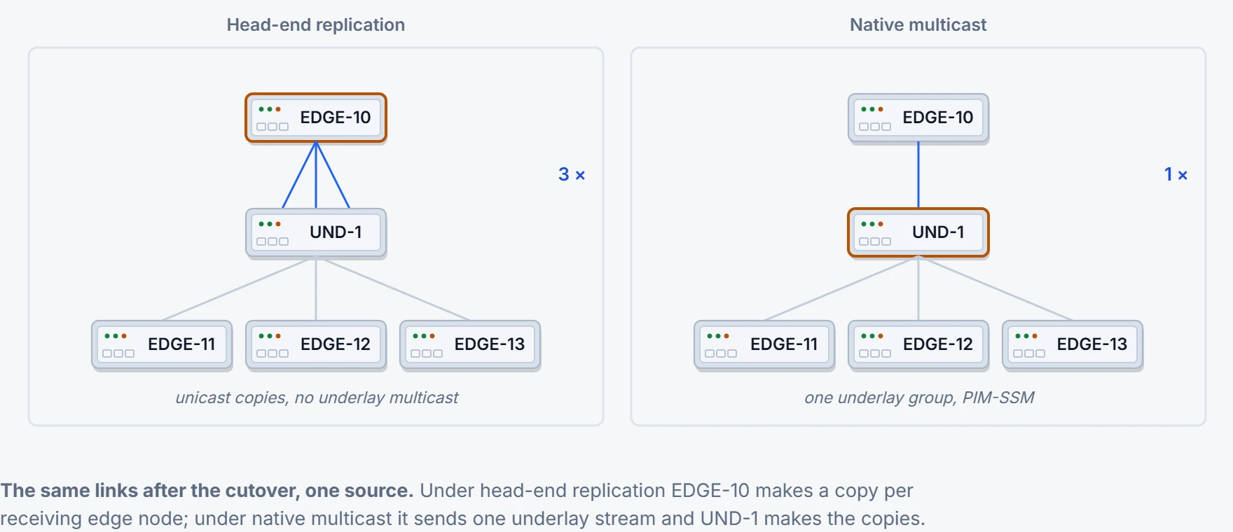
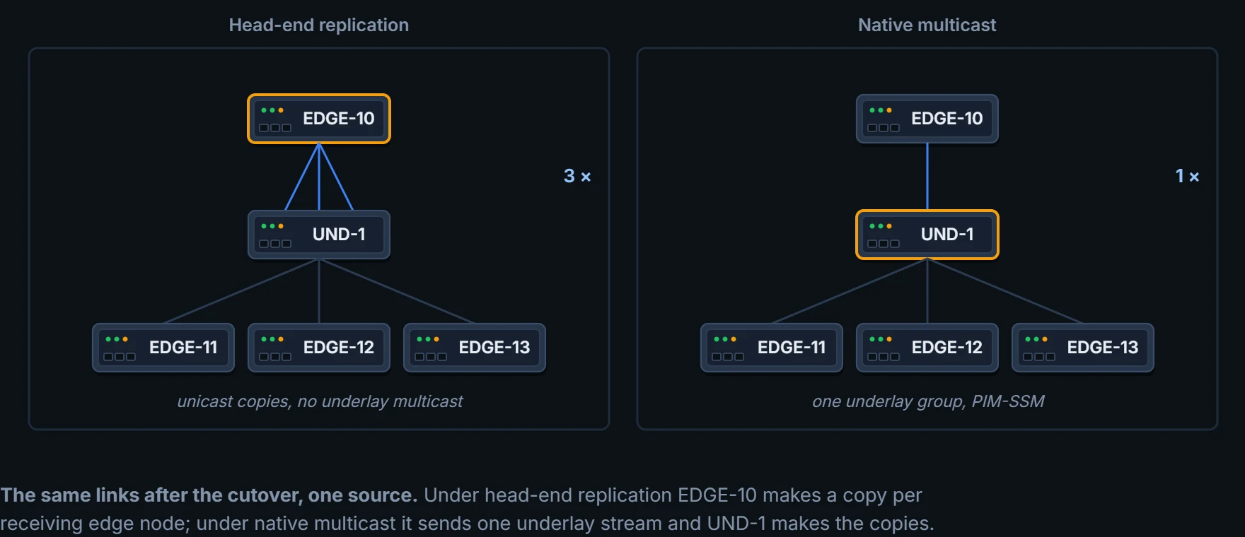
EDGE-10 to UND-1    3       unicast, one per receiving edge node per source
UND-1 to BORDER-1   0       nothing after the cutover
UND-1 to EDGE-11    1       unicast
UND-1 to EDGE-12    1       unicast
UND-1 to EDGE-13    1       unicast

FHR replications    3 per packet
branched by         EDGE-10
Look at the EDGE-10 to UND-1 row. Three unicast copies on one link, and BORDER-1 is out of the path.
Three receivers, three copies, one link, one router doing all of it. Now picture the same row with three hundred receivers. The first-hop router has effectively become the print room for the whole fabric, and every copy it makes goes down the same uplink it already had.
That is the entire scale argument, and it is worth sitting with before you read the next section. Nothing here is broken. It works exactly as documented. It just does not divide the work, and the device it does not divide the work for is the one closest to the source.
So what does a first-hop router's own entry show after the cutover?
From elsewhere, excerpted: the first-hop router’s overlay entries after the cutover. The flags legend above each entry is left out; every line shown comes from elsewhere, with its own annotations, hostnames and addresses.
Edge-1#show ip mroute vrf blue_vn 239.1.1.1
(*, 239.1.1.1), 5d01h/stopped, RP 10.47.6.1, flags: SCF
Incoming interface: LISP0.4100, RPF nbr 10.47.1.10
Outgoing interface list:
Vlan1025, Forward/Sparse-Dense, 5d01h/00:01:40, flags:

(10.47.7.2, 239.1.1.1), 01:53:06/00:02:42, flags: FT <-- Unicast Source
Incoming interface: Vlan1025, RPF nbr 0.0.0.0
Outgoing interface list:
LISP0.4100, 10.47.1.13, Forward/Sparse, 00:14:22/00:03:07, flags: <-- Edge-2's RLOC
Look at the last line. The outgoing entry is LISP0.4100, 10.47.1.13: an RLOC, nothing else. That is one unicast copy to one edge node.
Proves: that the first-hop router's (S,G) forwards out the LISP interface to an RLOC, which is a unicast copy to that edge node. Does not prove: that the edge node at that RLOC receives the traffic, or how many other copies the first-hop router is making.
A configuration from elsewhere, excerpted: the head-end edge node’s LISP interface. The lines come from elsewhere, in their own order.
interface LISP0.4100
vrf forwarding blue_vn
ip pim sparse-mode
end
Notice what is not on it. No transport line and no core group range: nothing on this interface refers to an underlay group.
What does a second source cost?
The FHR edge node must replicate each multicast packet to the other 25 edge nodes. This replication is performed per source, and packets are sent across the overlay. A second source means another 25 unicast replications.
Computed from the state: a second source behind the same edge node. No command prints it.
transport           head-end replication, after the cutover
sources             2

link                copies  what they are
SRC-1 to EDGE-10    2       multicast frames from the sources
EDGE-10 to UND-1    6       unicast, one per receiving edge node per source
UND-1 to BORDER-1   0       nothing after the cutover
UND-1 to EDGE-11    2       unicast
UND-1 to EDGE-12    2       unicast
UND-1 to EDGE-13    2       unicast

FHR replications    6 per packet
branched by         EDGE-10
Six on the same link, and EDGE-10 makes all of them. Nothing about the receivers changed.
The advantage of head-end replication is that it operates entirely in the overlay and does not require multicast in the underlay network. This mode makes it suitable for environments where underlay multicast cannot be enabled and creates a complete decoupling of the virtual and physical networks from a multicast perspective. However, if there are many LHRs, this can create high overhead on the FHRs, consuming additional CPU and bandwidth resources. Network designers should consider native multicast due to its efficiency and the reduction of load on the FHR fabric node.
So which does the guide lean toward? Native multicast, for efficiency. Head-end replication keeps the case where underlay multicast cannot be enabled.
Native multicast
What changes when the underlay carries it?
SDA Native Multicast is a form of overlay multicast, which is used to carry multicast traffic between fabric devices, encapsulating multicast traffic into another multicast group. Native multicast does not require the ingress fabric node to do unicast replication. Rather, the whole underlay, including intermediate nodes, is used to do the replication. To support native multicast, the FHRs, LHRs, and all network infrastructure between them must be enabled for multicast. Native multicast requires multicast to be enabled in the underlay but significantly reduces the replication load on the FHR, making it the preferred choice from an efficiency and scalability standpoint. It uses PIM-SSM for the underlay multicast transport. The overlay multicast messages are tunneled inside underlay multicast messages. This behavior also allows overlap in the overlay and underlay multicast groups in the network, if needed.
Now switch campus_vn to native multicast, with UND-1 running no multicast. What reaches the receivers?
Computed from the state: native multicast with no multicast on UND-1. No command prints it.
edge node   RLOC         receives
EDGE-11     10.60.1.11   nothing
EDGE-12     10.60.1.12   nothing
EDGE-13     10.60.1.13   nothing

native multicast needs the FHR, the LHRs and all infrastructure between them
enabled for multicast
Nothing. The requirement is every device between the first-hop and last-hop routers, not only the fabric nodes.
Computed from the state: the same, with multicast enabled across the underlay. No command prints it.
transport           native multicast, after the cutover
sources             1

link                copies  what they are
SRC-1 to EDGE-10    1       multicast frames from the sources
EDGE-10 to UND-1    1       one underlay stream per source
UND-1 to BORDER-1   0       nothing after the cutover
UND-1 to EDGE-11    1       underlay multicast
UND-1 to EDGE-12    1       underlay multicast
UND-1 to EDGE-13    1       underlay multicast

FHR replications    1 per packet
branched by         UND-1
Look at the EDGE-10 to UND-1 row again. One stream. UND-1, with no fabric role, branches it.
A configuration from elsewhere, excerpted: the native edge node’s LISP interface. The lines come from elsewhere, in their own order.
interface LISP0.4100
ip pim lisp transport multicast
ip pim lisp core-group-range 232.0.0.1 1000
Look at the third line. A core group range: this is where the underlay groups come from. Which address in the range an overlay group gets is not stated on these pages, so this page does not compute one for the scenario.
And under native multicast, what does the first-hop router's entry send to?
From elsewhere, excerpted: the first-hop router’s overlay entries. The flags legend above each entry is left out; every line shown comes from elsewhere, with its own annotations, hostnames and addresses.
Continue the lesson
The whole lesson, with its drawings and its questions. The rest of this section and 5 more after it.