
LAN automation and PnP
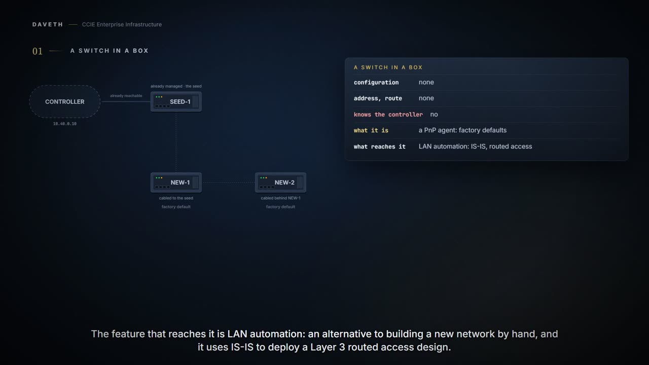
A switch arrives in a box with no configuration and no route. LAN automation in Catalyst Center reaches it through a seed device you already manage. Starting a session pushes loopback and IS-IS configuration to the seeds and a temporary configuration to the primary seed. The new switch, with every port in VLAN 1, sends DHCP discover; the seed answers from the LAN automation pool.
By Arif, founder of Daveth · Updated
The full 7 min walkthrough is in Daveth Pro (Network). See what the plan opens
What this page answers
What is a LAN automation seed device?
A predeployed switch already in the network, and the initial point through which LAN automation discovers and onboards new switches downstream. It must be reachable and managed before a session starts. Read it in “The seed, and the pool it hands out”
How does a PnP switch with no configuration get an address?
With no configuration all its ports are in VLAN 1, so it sends DHCP discover messages to the seed device, which offers an address from the LAN automation pool, with option 43 telling it where to call. Read it in “What a factory switch does”
What does starting LAN automation configure?
Loopback and IS-IS configuration on the primary and peer seed devices, plus a temporary configuration, including a DHCP server, on the primary seed so switches with no configuration can be reached. Read it in “What starting pushes”
A switch in a box
A switch arrives in a box. It has no configuration, no address and no route anywhere, and nothing has ever told it that Catalyst Center exists. How does a controller configure a switch it cannot reach?
The PnP agent is a Cisco Catalyst switch with factory default settings.
That is what Cisco calls the switch in the box, and the feature that reaches it is LAN automation:
Catalyst Center provides LAN automation as an alternative for manual deployment of new networks. LAN automation uses the IS-IS routing protocol to deploy a Layer 3 routed access design.
Notice what the second sentence leaves out. It names the routing protocol and the design, and it does not say why IS-IS. Neither does any page this lesson cites, so this page does not either.
One limit before anything else, because this course is dual stack by default. The pool this workflow reserves can be dual stack, and then:
LAN automation uses only the IPv4 subnet.
So everything below is IPv4: the pool, the temporary DHCP server and the routed links, in the 2.3.7.x user guide this lesson cites.
The seed, and the pool it hands out
What has to exist before a session can start? One switch you already manage.
Which is the first thing to say plainly about zero touch: it has a preflight checklist. The name describes what happens to the switches in the boxes, not to the engineer. Something has to already be reachable, configured and trusted before any of them can be found at all.
The seed device is a predeployed system in the network and is the initial point through which LAN automation discovers and onboards new switches downstream. Device discovery happens only on the primary seed device interfaces.
The deployment guide gives that switch a checklist. Five of its lines decide whether this lesson’s session starts:
Ensure that the system MTU (maximum transmission unit) value is at least 9100. Turn on IP routing on the seed devices. Set up routing between the seed service and Catalyst Center so that Catalyst Center has IP reachability to the LAN IP pool subnet. LAN automation works only when the ports are Layer 2. Ensure that the seed devices don't have any other interfaces connected to another DHCP server running in VLAN 1.
Computed from the state: SEED-1 against those five guidelines. No command prints it.
seed guideline                          SEED-1        met?
system MTU at least 9100                9100          yes
IP routing on                           on            yes
Catalyst Center reaches the LAN pool    routed        yes
discovery port is Layer 2               Layer 2       yes
no other DHCP server in VLAN 1          none          yes
Look at the fourth row. The deployment guide names one platform where it fails out of the box:
The ports on the Cisco Catalyst 6000 Series Switches are Layer 3 by default.
Then the pool. How big does the LAN pool have to be, and how much of it does the temporary DHCP server take?
The size of the LAN automation IP address pool must be at least 25 bits of netmask or larger. For example, if the parent pool is 192.168.10.0/24, a /26 subpool is allocated for the DHCP server. Therefore, a /24 pool reserves 64, a /23 pool reserves 128, a /22 pool reserves 256, and larger pools reserve 512 IP addresses for the DHCP server. To start LAN automation, the pool size must be atleast /25, which reserves a /27 pool or 32 IP addresses for the DHCP pool.
Computed from the state: the DHCP reservation for each LAN pool size. No command prints it.
LAN pool    DHCP reserves   as a prefix   sessions from one pool
/26         –               –             none, smaller than /25
/25         32              /27           one
/24         64              /26           repeated
/23         128             /25           repeated
/22         256             /24           repeated
/21         512             /23           repeated
Look at the last column. A /25 starts a session and is enough for exactly one:
Every time you start LAN automation, it checks for 64 available IP addresses in the IP pool. If you decide to run LAN automation multiple times with the same pool, use at least a /24 pool. If you plan to LAN automate only once for the IP pool, a /25 pool suffices.
This lesson reserves a /24, so its DHCP server takes a /26 and the pool is large enough for a second session. It is going to need one.
And a pool can be the right size and still fail:
If the pool is too fragmented, it cannot allocate the DHCP pool and the LAN automation session ends with an IP pool allocation error.
Notice what that sentence does not give you: how fragmented is too fragmented. The page puts no number on it.
What starting pushes
What lands on SEED-1?
pushes the loopback and IS-IS configuration to the primary and peer seed devices and the temporary configuration to the primary seed device, enabling discovery and onboarding of the PnP agent.
Two kinds of configuration, and the page calls only one of them temporary. The temporary part is what makes a switch with no configuration reachable, and the Start page prints all of it. The DHCP server first:
From elsewhere: the primary seed’s DHCP pool. The values in it come from elsewhere, not from this scenario.
ip dhcp pool nw_orchestration_pool
  network 10.4.218.0 255.255.255.192
  option 43 ascii 5A1D;B2;K4;I10.4.249.241;J80;
  default-router 10.4.218.1
  class ciscopnp
    address range 10.4.218.2 10.4.218.62
!
ip dhcp class ciscopnp
  option 60 hex 636973636f706e70
!
ip dhcp excluded-address 10.4.218.1
!
Look at the option 43 line. The address after the I is where a new switch is going to call:
For DNA Center to provision your PnP agents, the DHCP configuration that the seed device receives must have option 43 defined with the IP address of the DNA Center enterprise-facing Network Interface Card (NIC) or the Virtual IP (VIP) address, if you have a n-node cluster.
Document 213927 was written for DNA Center, and the Start page prints the same option under Catalyst Center. Here is the same block for this lesson’s seed:
Drawn in the published layout: SEED-1’s DHCP pool, from a /24 LAN pool. The pool name, option 60 class and structure are the Start page's; Catalyst Center's address, the /24 LAN pool and the /26 carved from it are this course's own.
SEED-1# show running-config | section ip dhcp
ip dhcp pool nw_orchestration_pool
  network 10.40.8.0 255.255.255.192
  option 43 ascii 5A1D;B2;K4;I10.40.0.10;J80;
  default-router 10.40.8.1
  class ciscopnp
    address range 10.40.8.2 10.40.8.62
!
ip dhcp class ciscopnp
  option 60 hex 636973636f706e70
!
ip dhcp excluded-address 10.40.8.1
!
Look at the address range line. A /26 from .2 to .62, with .1 excluded and set as the default router: the same shape as the published sample.
Only the addresses changed. What 5A1D, B2, K4 and J80 mean is not explained on the pages this lesson cites, and this page does not supply it.
Proves: that the temporary DHCP pool is on the seed, with the option 43 string, the default router and the address range it hands out. Does not prove: that any switch has taken an address from it, that the address in option 43 is reachable from the switches, or which devices the controller has discovered.
Then the seed’s end of a Layer 2 network: an address on VLAN 1, and every discovery port made an access port in it.
From elsewhere: the primary seed’s VLAN 1. The values in it come from elsewhere, not from this scenario.
vlan 1
!
interface Vlan1
  ip address 10.4.218.1 255.255.255.192
  no shutdown
  ip router isis
  clns mtu 1400
   bfd interval 500 min_rx 500 multiplier 3
   no bfd echo
exit
!
In Catalyst Center Release 2.3.7.5 and later, the clns mtu value is configured as 1492 instead of 1400.
Look at the clns mtu line in that sample. It is the value from before 2.3.7.5, and this lesson names only 2.3.7.x, so VLAN 1 is not drawn for SEED-1.
From elsewhere: a discovery interface on the primary seed. The values in it come from elsewhere, not from this scenario.
interface TenGigabitEthernet1/1/8
  switchport
  switchport mode access
  switchport access vlan 1
!
interface TenGigabitEthernet1/1/7
   switchport
   switchport mode access
  switchport access vlan 1
exit
Each discovery interface on the primary seed device gets this configuration.
The Layer 2 stage is temporary. A DHCP server on a switch you run in production, and access ports in VLAN 1 on the links you meant to route.
And the controller has to reach that VLAN 1 address itself:
LAN automation configures an IP address on the seed device of VLAN 1. If this VLAN 1 IP address of the seed device is not reachable from Catalyst Center, an error message is displayed on the LAN Automation Status window.
So which address does that error name? SEED-1’s own VLAN 1 address, not any new switch’s.
What a factory switch does
NEW-1 powers on with nothing. What does it do?
When PnP agents boot up, they have no configuration. Therefore, all of their ports are part of VLAN 1. Consequently, the devices send DHCP discover messages to the seed device. The seed device answers with an offer of the IP addresses within the LAN automation pool.
That is the whole bootstrap. The seed was built to answer the DHCP discover a switch with no configuration sends, and option 43 in the answer tells it where to call.
Next, the PnP agent image is upgraded and basic configurations such as loopback address, system MTU, and IP routing are pushed to the PnP agent. The image is updated only if a golden image is marked for that switch type in Catalyst Center under Design > Image repository.
Why would two switches in one session finish at different times? One of them may have an image to install first, and this lesson’s second switch does.
Computed from the state: the session once NEW-1 is managed. No command prints it.
session                 1, seeded from SEED-1, running
temporary DHCP, VLAN 1  on SEED-1

switch  hops  where it is                         its uplink
NEW-1   1     managed in the inventory            access ports in VLAN 1
NEW-2   2     factory default, no address         access ports in VLAN 1
Look at NEW-1’s uplink column. It is managed, and its uplink is still the access port the seed put in VLAN 1. Nothing is routed yet.
Now NEW-2, cabled behind NEW-1. Is two hops too far?
LAN automation initiates only on directly connected neighbors. LAN automation in Catalyst Center supports a maximum of two hops from the initial automation boundary point device. Any additional network devices beyond two hops might be discovered but cannot be automated.
The user guide sets the limit with a field, and gives that field a higher ceiling:
Devices are LAN automated up to the specified level under the primary seed device. The default value for Discovery Depth is 2, and the maximum value is 5. The connection between Discovered device 2 and Discovered device 3 is not configured as part of the LAN automation job because it is more than two hops away from Primary device.
Both sentences are on the same page. A Discovery Depth that goes to 5, and a device three hops out whose link is not configured. This page does not reconcile them; NEW-2 is at two, where every page agrees.
How NEW-2’s DHCP request reaches the seed through NEW-1 is not described on these pages, so the walk shows that it is discovered and not how.
Computed from the state: the session with NEW-2 discovered. No command prints it.
session                 1, seeded from SEED-1, running
temporary DHCP, VLAN 1  on SEED-1

switch  hops  where it is                         its uplink
NEW-1   1     managed in the inventory            access ports in VLAN 1
NEW-2   2     image upgrade in progress           access ports in VLAN 1
Look at the hops column. Two, which is the limit every page agrees on.
NEW-2 is discovered and not managed. A golden image is marked for its switch type, so its configuration waits for the upgrade.
While the session runs, the seed answers more than the ports you chose:
Otherwise, the PnP agents connected to Floor-2 might also get DHCP IPs from the server running on the primary seed device. Therefore, we recommend that you shut down other discovery interfaces.
And a peer seed does not move the DHCP server:
Catalyst Center configures the DHCP server on the primary device.
Continue the lesson
The whole lesson, with its drawings and its questions. 4 more sections after the ones above.