
Ethernet and Switch CLI Lab
A hands-on CCNA lab, with every output printed so it works without equipment. The ticket says PC-A cannot ping PC-B. Read the switch first with show commands, which change nothing, then name it, put both PCs in VLAN 10, save the configuration, and follow the four frames of the first ping through the switch.
By Arif, founder of Daveth · Updated
The full 10 min walkthrough is in Daveth Pro (Network). See what the plan opens
The work order
This is a lab page. Do it on your own lab from 00.2 if you have one; if not, every output you'd see is printed here, and the questions still work. The outputs follow the switch command line used throughout this course. Yours may differ in spacing or columns, so judge each one by what it means, not by where the characters sit.
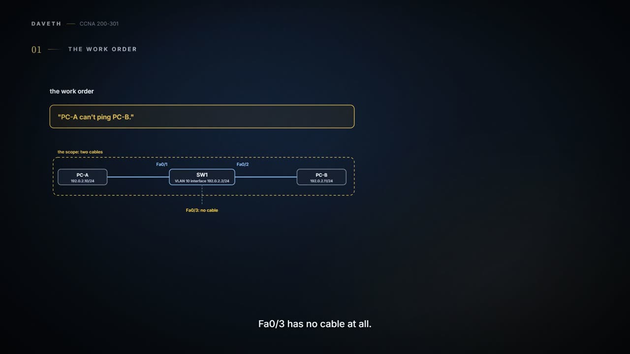
The ticket reads: "PC-A can't ping PC-B." No drawing, no detail. So the first job is scope: which device, which cables, which ports. Draw them on paper before typing anything, then compare with the drawing below.
| Reported | "PC-A can't ping PC-B." |
|---|---|
| Scope | SW1, and the two cables in use: PC-A on Fa0/1, PC-B on Fa0/2. Fa0/3 has no cable. |
| Goal | PC-A and PC-B in VLAN 10, pinging each other; SW1 reachable on 192.0.2.2; the configuration saved. |
| Hand back | a five-item evidence ticket (at the end of this page) |
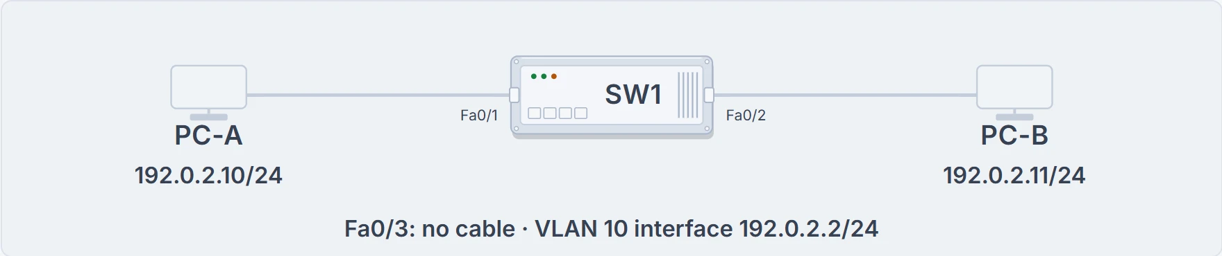
The lab for this work order: PC-A on Fa0/1, PC-B on Fa0/2, Fa0/3 with no cable, and SW1's own VLAN 10 interface.
The switch has 24 ports. Our mystery has two cables. There's no need to interrogate all 24, TV-detective style.
Read before you touch
Start in user EXEC mode (the > prompt), then enable to reach privileged EXEC (#). Every show command is an observation: it reports and changes nothing, so it's always safe to run first. The switch is still at its factory settings, so its prompt still says Switch, and every port is in VLAN 1.
Switch> enable
Switch# show interfaces status
Port      Name               Status       Vlan       Duplex  Speed Type
Fa0/1                        connected    1          a-full  a-100 10/100BaseTX
Fa0/2                        connected    1          a-full  a-100 10/100BaseTX
Fa0/3                        notconnect   1            auto   auto 10/100BaseTX
! (Fa0/4 to Fa0/24 omitted: nothing is plugged into them)
Switch# show mac address-table dynamic
          Mac Address Table
-------------------------------------------

Vlan    Mac Address       Type        Ports
----    -----------       --------    -----
Total Mac Addresses for this criterion: 0
notconnect for Fa0/3, connected for the two ports with cables. And the MAC table is empty, because the switch has just restarted and neither PC has sent anything yet. In a real lab, the PCs often send something on their own soon after they're cabled, so don't be surprised to find entries; either way, you now know what "before" looked like.
Set it up, then save it
If VLANs still feel new, treat the VLAN lines below as done for you and keep your eyes on the evidence; the VLAN work gets its own lab next. The work order wants both PCs in VLAN 10 and SW1 reachable on 192.0.2.2. From privileged EXEC, configure terminal enters global configuration. The setup names the switch, creates VLAN 10 and names it, labels each port with a description, makes Fa0/1 and Fa0/2 access ports in VLAN 10, and gives SW1 its own address on the VLAN 10 interface. Then copy running-config startup-config saves it. Watch the prompt change as the modes change, and as the hostname does. The VLAN 10 interface is SW1's own place in VLAN 10: like any device in that VLAN, it receives the VLAN's broadcasts.
Switch> enable
Switch# configure terminal
Enter configuration commands, one per line.  End with CNTL/Z.
Switch(config)# hostname SW1
SW1(config)# vlan 10
SW1(config-vlan)# name LAB
SW1(config-vlan)# interface FastEthernet0/1
SW1(config-if)# description PC-A
SW1(config-if)# switchport mode access
SW1(config-if)# switchport access vlan 10
SW1(config-if)# interface FastEthernet0/2
SW1(config-if)# description PC-B
SW1(config-if)# switchport mode access
SW1(config-if)# switchport access vlan 10
SW1(config-if)# interface vlan 10
SW1(config-if)# ip address 192.0.2.2 255.255.255.0
SW1(config-if)# no shutdown
! (status messages omitted: the VLAN 10 interface coming up)
SW1(config-if)# end
SW1# copy running-config startup-config
Destination filename [startup-config]?
! (Return accepts the name in brackets; the switch confirms the save)
Then check it, rather than trusting the typing:
SW1# show vlan brief
VLAN Name                             Status    Ports
---- -------------------------------- --------- -------------------------------
1    default                          active    Fa0/3, Fa0/4, ...
10   LAB                              active    Fa0/1, Fa0/2
1002 fddi-default                     act/unsup
1003 token-ring-default               act/unsup
1004 fddinet-default                  act/unsup
1005 trnet-default                    act/unsup
! (in VLAN 1, Fa0/4 onwards shortened to "...")
SW1# show running-config interface FastEthernet0/1
Building configuration...
! (the header lines omitted)
!
interface FastEthernet0/1
 description PC-A
 switchport access vlan 10
 switchport mode access
end
SW1# show startup-config
! (the header lines omitted: an excerpt)
hostname SW1
! (lines omitted)
interface FastEthernet0/1
 description PC-A
 switchport access vlan 10
 switchport mode access
! (more lines omitted)
VLAN 10, named LAB, now owns Fa0/1 and Fa0/2; Fa0/3 stays in VLAN 1. The running configuration for Fa0/1 shows the lines that were typed (the switch lists them in its own order), and the startup configuration now holds them too.
They're gone. Everything typed changes the running configuration, in memory; a restart loads the startup configuration, so only what was copied there comes back. That's why the save sits at the end of the setup, not "later". (VLAN definitions can behave differently: many switches keep them in a separate file, vlan.dat, as soon as they're created. The hostname and the port settings don't get that treatment.)
Follow the frames
Now the ping. PC-A has never talked to PC-B, so before the ping itself it has to find PC-B's MAC address with ARP: a broadcast asking who has 192.0.2.11. Four frames make up the first exchange. For each one, predict where SW1 sends it, then check.
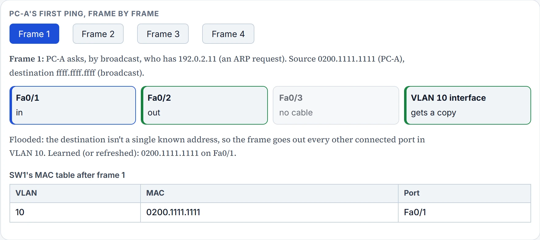
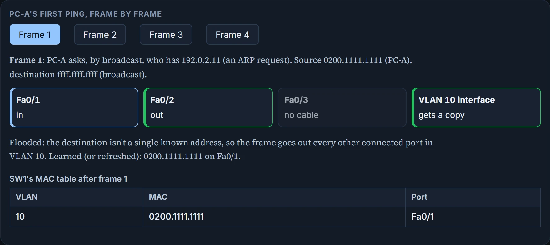
Out Fa0/2, plus a copy to SW1's own VLAN 10 interface, which ignores it: the question was about 192.0.2.11, not 192.0.2.2. Fa0/3 gets nothing, having no cable and sitting in VLAN 1 anyway. Over the remaining frames: PC-A is learned from frame 1, PC-B from frame 2, and from frame 2 on, each frame goes out exactly one port.
The switch writes down where a sender lives; it doesn't ask the sender for a business card.
You can think of the MAC table as the visitors' log at reception: who came in, and through which entrance. (Where it stops: SW1 writes the entries itself, from each frame's source address, and they fade after five minutes of silence by default; nobody signs anything.)
Continue the lesson
The whole lesson, with its drawings and its questions. 3 more sections after the ones above.