
Wireless LAN and WLC Lab
A simulated CCNA wireless lab. A lightweight AP in local mode joins the controller over CAPWAP from its management VLAN, and every WLAN it serves travels inside that tunnel. On the controller, check the AP has joined, create the dynamic interface for the clients' VLAN, create the WLAN and map it to that interface, then set WPA2 with AES and a PSK.
By Arif, founder of Daveth · Updated
The full 10 min walkthrough is in Daveth Pro (Network). See what the plan opens
What this page answers
How do you configure a WLAN on a WLC?
Check the AP list first: the AP must show as joined. Create the dynamic interface for the VLAN, create the WLAN and map it to that interface, then set its security, such as WPA2 with AES and a PSK. Read it in “The controller's pages”
The requirement
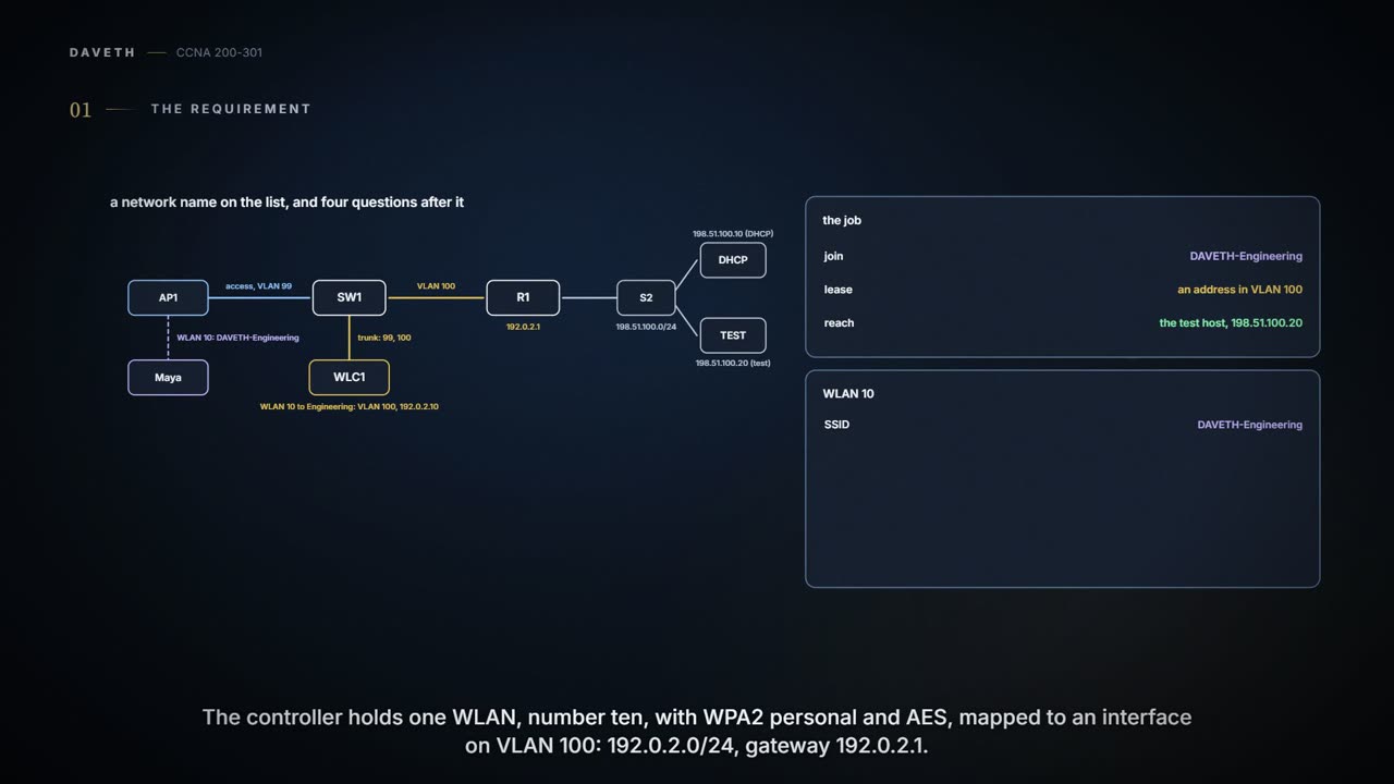
A lab page; the switch outputs follow the command line used throughout this course, and the controller's pages are drawn by the course from the labels in 03.5.4. This is a simulated controller lab, not a live change. AP1 joins the controller, WLC1, over CAPWAP from VLAN 99. One WLAN, ID 10, profile and SSID DAVETH-Engineering, uses WPA2-Personal with AES and maps to an interface on VLAN 100, 192.0.2.0/24, gateway 192.0.2.1. Maya's laptop has to join, lease an address, and reach the test host 198.51.100.20. The key is shared out of band and never appears on this page. In this lab, WLC1 relays each client's DHCP request to the interface's DHCP server, and that server has a 192.0.2.0/24 pool that leaves out .1 and .10; WLC1's management interface is tagged VLAN 99.
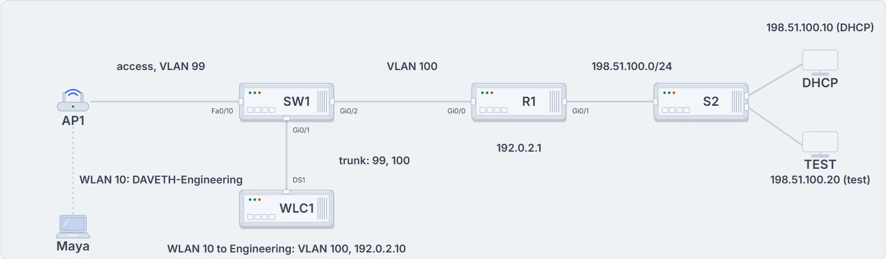
Maya on AP1's radio; AP1 on an access port; WLC1 on a trunk; R1 the VLAN 100 gateway; the DHCP server and the test host behind R1.
Only that an AP is sending beacons for DAVETH-Engineering. Whether Maya's key works, which VLAN the laptop's traffic lands in, whether it gets an address and whether anything answers are four separate questions, and the rest of this page takes them one gate at a time.
The sign is lit. Nobody has checked yet whether there's a room behind it. (Where it stops: a beacon says a little more than a sign does; it also advertises the security the WLAN expects.)
Two cables, two jobs
Build the wired side before touching the controller. AP1 and WLC1 both plug into SW1, and they need different ports.
SW1# configure terminal
Enter configuration commands, one per line.  End with CNTL/Z.
SW1(config)# vlan 99
SW1(config-vlan)# name AP-MGMT
SW1(config-vlan)# vlan 100
SW1(config-vlan)# name ENGINEERING
SW1(config-vlan)# exit
SW1(config)# interface FastEthernet0/10
SW1(config-if)# description AP1
SW1(config-if)# switchport mode access
SW1(config-if)# switchport access vlan 99
SW1(config-if)# interface GigabitEthernet0/1
SW1(config-if)# description WLC1 distribution port
SW1(config-if)# switchport mode trunk
SW1(config-if)# switchport trunk allowed vlan 99,100
SW1(config-if)# interface GigabitEthernet0/2
SW1(config-if)# description R1, VLAN 100 gateway
SW1(config-if)# switchport mode access
SW1(config-if)# switchport access vlan 100
SW1(config-if)# end
SW1# show interfaces trunk
Port        Mode             Encapsulation  Status        Native vlan
Gi0/1       on               802.1q         trunking      1

Port        Vlans allowed on trunk
Gi0/1       99,100
! (the rest is left out)
AP1 is a lightweight AP in local mode. Every WLAN it serves travels inside the CAPWAP tunnel to WLC1, so the AP needs only an access link, here in VLAN 99, its management VLAN. WLC1's distribution system port is different: it carries the management traffic and the client VLANs, so SW1 Gi0/1 is a trunk allowing 99 and 100, and AP1's CAPWAP tunnel reaches WLC1 in VLAN 99 over that same trunk. Both VLANs exist on SW1, and Gi0/2 puts R1 in VLAN 100. show interfaces trunk proves which VLANs may cross that cable. It doesn't prove AP1 has joined, or that any key works.
Both cables end in SW1, and they do different jobs: don't wire them the same way.
The controller's pages
On WLC1, the work comes in five steps. Check the AP list first: AP1 has to show as joined, or nothing else matters. Then create the dynamic interface: Engineering, VLAN 100, bound to the distribution port, its address, mask and gateway, and the DHCP server WLC1 will relay clients' requests to. Then create WLAN 10 and map it to that interface. Then set WPA2 with AES and a PSK, typed privately into the lab's controller and never written down here. Last, make sure the WLAN is enabled, apply, and read the WLANs list.
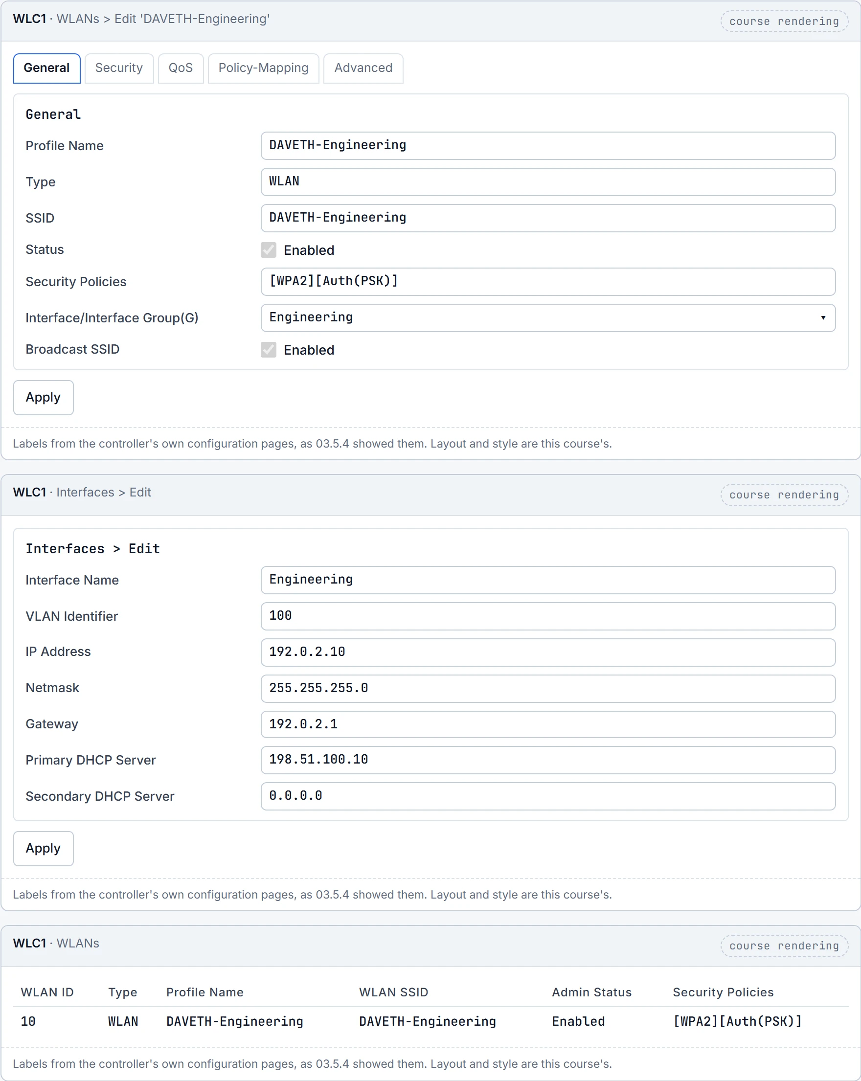
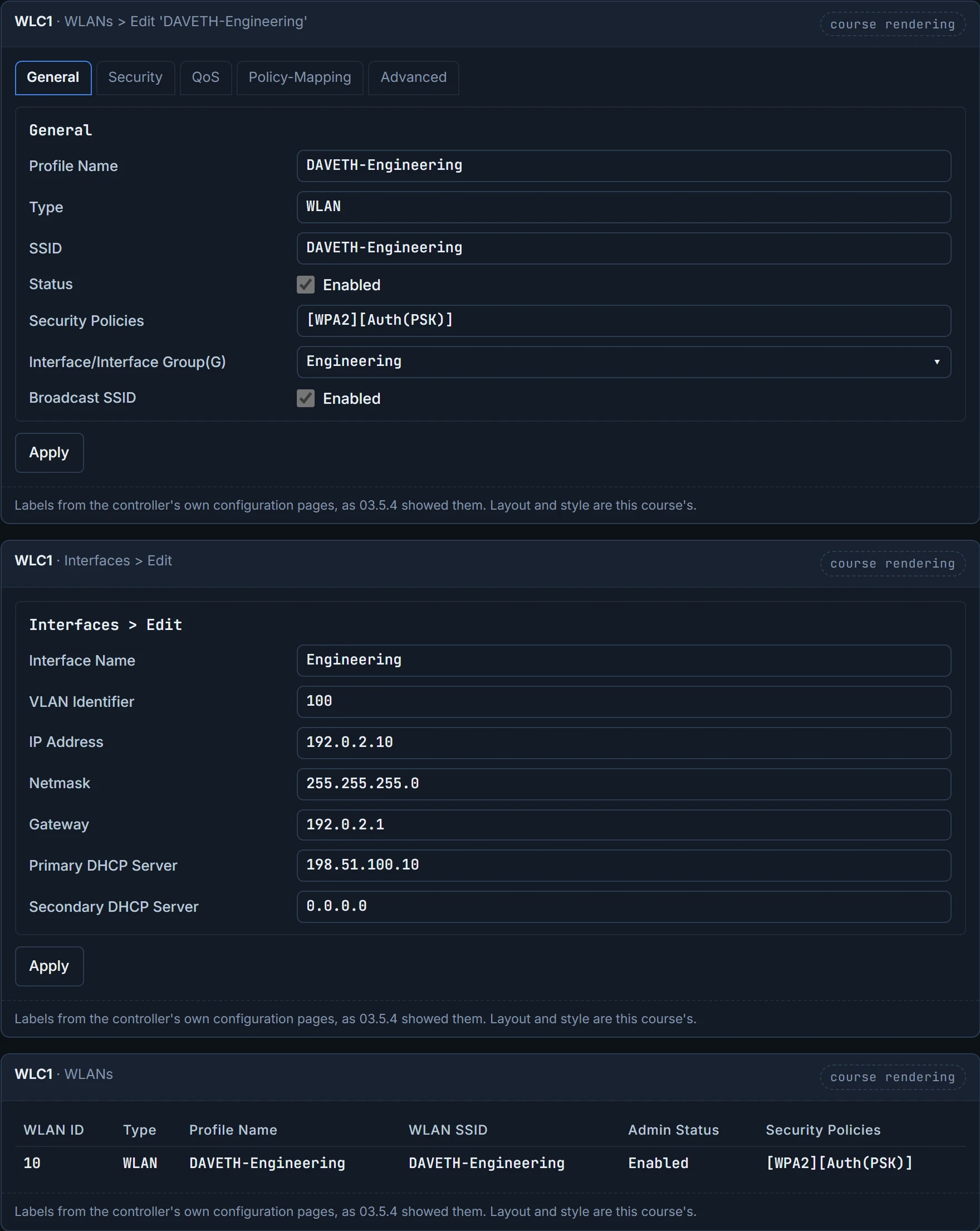
The WLAN's Interface setting names Engineering, and the interface's VLAN Identifier is 100: that pair is what puts Maya in VLAN 100. The WLANs list proves WLAN 10 is enabled with WPA2 and a PSK. AES is set on the WLAN's Security tab, as 03.5.4 walked through; the tag in the list doesn't show the cipher. The list doesn't prove the key Maya has matches, and the PSK field is masked, so the pages can't show you that either. The labels here are the classic controller's, as 03.5.4 showed them; newer controllers lay the same ideas out on different pages, so follow the lab's own screens for the exact clicks.
Continue the lesson
The whole lesson, with its drawings and its questions. 4 more sections after the ones above.