
DHCP, NAT and IP Services Lab
A hands-on CCNA services lab. PC-A gets its address from a DHCP server through a relay, reaches its gateway, then needs a default route and PAT, with ip nat inside and outside marked, to reach a web host behind one public address. Both routers then take their time from NTP and send their logs to the same collector, each checked separately.
By Arif, founder of Daveth · Updated
The full 13 min walkthrough is in Daveth Pro (Network). See what the plan opens
The requirement
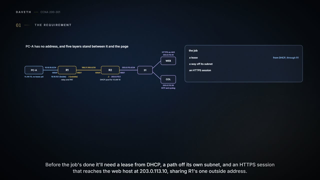
A lab page; the outputs follow the command line used throughout this course. PC-A sits in VLAN 10, 10.10.10.0/24, and has no address yet. It needs one from DHCP, a way off its subnet, and a working HTTPS session to the web host at 203.0.113.10, behind R1's single outside address. Both routers also need the right time and somewhere to send their logs: the collector at 203.0.113.50. WEB and COL use R2, 203.0.113.1, as their default gateway. All the addresses here come from ranges set aside for documentation and labs.
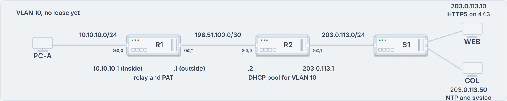
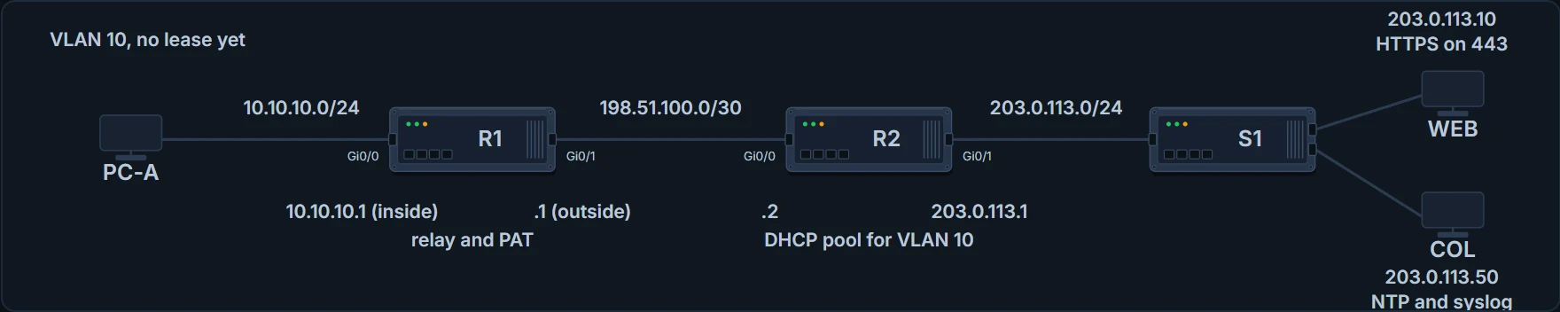
PC-A, R1 (the relay and the PAT router), R2 (the lab's DHCP server), and the server LAN with WEB and COL.
R2 plays the upstream router and the DHCP server in this lab. That's a lab arrangement, not a claim about how a real provider runs anyone's campus.
Start with the lease. PC-A has no address, so it can't reach even its own gateway, and NAT hasn't had a single packet to translate yet. The order is lease, then gateway, then a route out, then the translation, then the application. Each layer rests on the ones before it.
The post office can't translate a return address the computer hasn't been given yet. (Where it stops: PC-A isn't waiting on NAT; it has no address to send from at all.)
First, a lease through the relay
R2 already has the lab's DHCP service set up. Writing a router's DHCP pool isn't something the exam asks of you, so read this card rather than type it:
R2# show running-config
! (lines left out)
interface GigabitEthernet0/0
 ip address 198.51.100.2 255.255.255.252
!
ip dhcp excluded-address 10.10.10.1 10.10.10.20
!
ip dhcp pool USERS
 network 10.10.10.0 255.255.255.0
 default-router 10.10.10.1
 dns-server 203.0.113.53
!
ip route 10.10.10.0 255.255.255.0 198.51.100.1
! (the rest is left out)
The pool leases from 10.10.10.0/24 and hands out gateway 10.10.10.1 and DNS server 203.0.113.53. The excluded range keeps .1 to .20 out of the pool, so the first lease is usually 10.10.10.21, the lowest free address, though a server doesn't promise which one you'll get. The DNS setting is just an option handed out; nothing in this lab tests DNS. And the static route matters more than it looks: R2 sends its replies to R1's address on PC-A's subnet, 10.10.10.1, so R2 needs a route to 10.10.10.0/24.
Now R1. One card holds everything R1 needs for the whole lab; the DHCP part is the ip helper-address line on Gi0/0:
R1# configure terminal
Enter configuration commands, one per line.  End with CNTL/Z.
R1(config)# interface GigabitEthernet0/0
R1(config-if)# ip address 10.10.10.1 255.255.255.0
R1(config-if)# ip helper-address 198.51.100.2
R1(config-if)# ip nat inside
R1(config-if)# no shutdown
R1(config-if)# interface GigabitEthernet0/1
R1(config-if)# ip address 198.51.100.1 255.255.255.252
R1(config-if)# ip nat outside
R1(config-if)# no shutdown
R1(config-if)# exit
R1(config)# ip route 0.0.0.0 0.0.0.0 198.51.100.2
R1(config)# access-list 1 permit 10.10.10.0 0.0.0.255
R1(config)# ip nat inside source list 1 interface GigabitEthernet0/1 overload
R1(config)# end
PC-A's Discover goes to 255.255.255.255, and R1 won't route that. The helper makes R1 change the source to its own 10.10.10.1 and the destination to 198.51.100.2, then route the packet to R2 like any other. The Discover and the Request go up that way. R2 sends the Offer and the Acknowledgment back to 10.10.10.1, and R1 passes them on to PC-A's LAN. R2 makes every choice.
You can think of the relay as a receptionist who takes a question shouted in the lobby and phones it through to the right office. (Where it stops: R1 answers nothing itself; it re-addresses the messages and lets the network carry them.)
R1# show ip interface GigabitEthernet0/0
GigabitEthernet0/0 is up, line protocol is up
  Internet address is 10.10.10.1/24
  Broadcast address is 255.255.255.255
  Address determined by non-volatile memory
  MTU is 1500 bytes
  Helper address is 198.51.100.2
! (the rest is left out)
The Helper address line proves R1 will relay; it doesn't prove R2 answered. For that, look at PC-A's settings, and at show ip dhcp binding on R2, which lists each address it has leased.
| Address | 10.10.10.21 (the lowest free address; yours may differ) |
|---|---|
| Mask | 255.255.255.0 |
| Default gateway | 10.10.10.1 |
| DNS server | 203.0.113.53 (a lab setting; nothing here tests DNS) |
| DHCP server | 198.51.100.2 |
It proved DHCP worked across the relay, and that R2's route back works: the Offer and the Acknowledgment made it home. Whether PC-A can reach anything past R1, whether it's translated, and whether DNS works are all still open.
The room key works; that doesn't mean the restaurant is open. (Where it stops: the lease also proved R2's route back, which is more than a key proves.)
Then a route, then a translation
A ping from PC-A to 10.10.10.1 proves the gateway. Past that, R1 needs a way out: the default route on the card, via R2.
R1# show ip route static
! (the legend and the header lines are left out)
S*       0.0.0.0/0 [1/0] via 198.51.100.2
Next, PAT. ip nat inside on Gi0/0 and ip nat outside on Gi0/1 tell R1 which side is which; only packets arriving on an inside interface create new translations. The last line translates inside sources permitted by ACL 1 to Gi0/1's own address, and overload lets many flows share it by port.
ACL 1 is a selector. ip nat inside source list 1 uses it to choose which inside local addresses get translated. It filters nothing, because it isn't applied to any interface.
Now open an HTTPS connection from PC-A to 203.0.113.10, and while it's open, look at R1:
R1# show ip nat translations
Pro  Inside global         Inside local          Outside local      Outside global
tcp  198.51.100.1:49152    10.10.10.21:49152     203.0.113.10:443   203.0.113.10:443
! (port numbers vary; the row is removed after a while with no traffic)
R1# show ip nat statistics
Total active translations: 1 (0 static, 1 dynamic; 1 extended)
! (the peak line is left out)
Outside interfaces:
  GigabitEthernet0/1
Inside interfaces:
  GigabitEthernet0/0
! (the rest is left out)
Read the row from the inside out: inside local 10.10.10.21:49152, PC-A's own address and port; inside global 198.51.100.1:49152, the same flow wearing R1's outside address; outside 203.0.113.10:443, the web host. Your port numbers will differ. The web host replies to 198.51.100.1:49152; R2 reaches that over the /30, and R1 uses the row to hand the reply back to 10.10.10.21:49152. A row appears with the flow's first packet out, and is removed after a while with no traffic (or by clear ip nat translation *), so capture it during the test: then you know it's that test's row. And ping 203.0.113.10 is a separate test: it creates an ICMP translation and proves the host answers, not that anything listens on port 443.
If you've ever posted a letter from work with the office's return address on it, PAT will feel familiar: the reply comes back to the office, and someone inside knows whose it is. (Where it stops: R1 knows by port number, not by name, and forgets once the flow has been quiet for a while.)
Two clocks, one collector
R1's clock has been set four minutes fast on purpose. Point both routers at the collector with ntp server 203.0.113.50 for time and logging host 203.0.113.50 for logs. That's one address running two separate services, and each needs its own check. R2 gets the same two lines; R1's side is shown here.
R1# show ntp status
Clock is unsynchronized
! (the rest of the line and the output are left out)
R1# show clock
14:25:05.118 UTC
! (the day and date are left out; four minutes fast)
R1# configure terminal
Enter configuration commands, one per line.  End with CNTL/Z.
R1(config)# ntp server 203.0.113.50
R1(config)# logging host 203.0.113.50
R1(config)# end
! (some minutes pass)
R1# show ntp status
Clock is synchronized, stratum 4, reference is 203.0.113.50
! (the rest is left out; stratum 4 because this lab's collector is stratum 3)
R1# show logging
! (the settings above it are left out)
       Logging to 203.0.113.50 (udp port 514, audit disabled,
           link up),
! (the rest is left out)
The ntp server line only says where to ask. show clock prints a time whether it's right or not. show ntp status is the evidence: unsynchronised at first, then synchronised with 203.0.113.50 as the reference, a few minutes later. show ntp associations gives the detail, with a * beside the server a router has synchronised to. For logs, show logging shows where R1 is set to send them; whether they arrive is a check you make on the collector itself.
Continue the lesson
The whole lesson, with its drawings and its questions. The rest of this section and 3 more after it.