
VLAN, Trunk and EtherChannel Lab
A hands-on CCNA lab: PC-A reaches PC-B but not PC-C. Build both switches the same way: VLANs 10, 20 and 99, the access ports, both gigabit ports in an LACP channel with mode active, and the trunk on the port-channel with native VLAN 99. Then follow one frame, tagged only on the trunk, from PC-A to PC-B.
By Arif, founder of Daveth · Updated
The full 10 min walkthrough is in Daveth Pro (Network). See what the plan opens
The work order
A lab page again: build it on your own gear or simulator if you can, or read the printed outputs and answer the questions. The outputs follow the switch command line used throughout this course; judge yours by meaning, not by spacing.
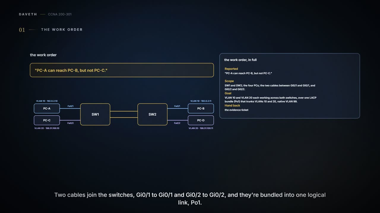
| Reported | "PC-A can reach PC-B, but not PC-C." |
|---|---|
| Scope | SW1 and SW2; the four PCs; the two cables between Gi0/1 and Gi0/1, and Gi0/2 and Gi0/2. |
| Goal | VLAN 10 and VLAN 20 each working across both switches, over one LACP bundle (Po1) that trunks VLANs 10 and 20, native VLAN 99. |
| Hand back | the evidence ticket at the end of this page |
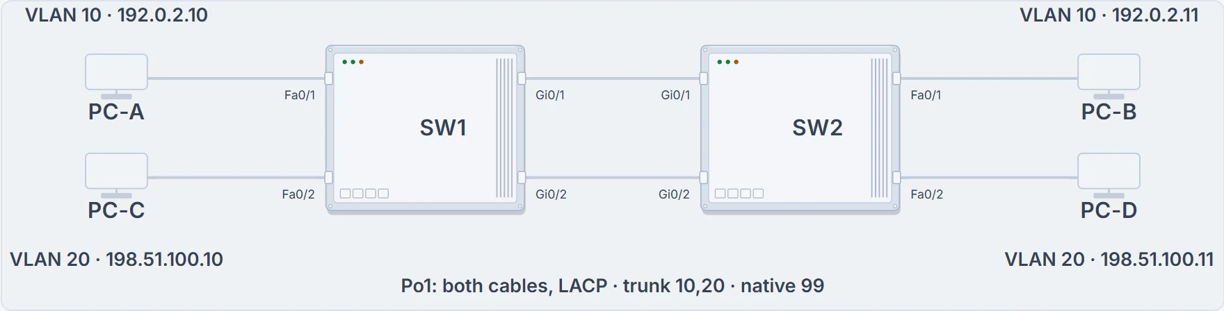
SW1 and SW2, two VLANs on each, and two cables bundled as Po1.
The report sounds like a fault. Before hunting for one, decide what should happen. PC-A and PC-B are both in VLAN 10; PC-C is in VLAN 20, on a different subnet too.
Expected. A VLAN is its own network, and a trunk carries several of them without mixing them; getting from one VLAN to another takes a router, which is a later lab's job. So the ticket's "not PC-C" goes on the evidence sheet as a correct result, with its reason.
The trunk carries two floors; it isn't a staircase between them.
Build both ends
Everything here happens on both switches. Each needs VLANs 10, 20 and 99; its two access ports; both gigabit ports in channel-group 1 with mode active, so LACP starts the bundle; and the trunk settings on the port-channel interface, Po1: trunk mode, native VLAN 99, allowed VLANs 10 and 20. Before a port joins the bundle, the switch checks it against the other members and against the neighbour: speed, duplex, access or trunk state, and for trunks the allowed list and native VLAN must all match. (On the neighbour side, spanning-tree settings are the exception.)
Two notes before typing. The channel-group number is local to each switch: SW2 could use another number, but using 1 on both keeps the evidence readable. And on switches that support more than one trunking protocol, switchport trunk encapsulation dot1q comes before switchport mode trunk; switches that only support 802.1Q don't need it.
SW1# configure terminal
Enter configuration commands, one per line.  End with CNTL/Z.
SW1(config)# vlan 10
SW1(config-vlan)# name LAB10
SW1(config-vlan)# vlan 20
SW1(config-vlan)# name LAB20
SW1(config-vlan)# vlan 99
SW1(config-vlan)# name NATIVE99
SW1(config-vlan)# interface FastEthernet0/1
SW1(config-if)# switchport mode access
SW1(config-if)# switchport access vlan 10
SW1(config-if)# interface FastEthernet0/2
SW1(config-if)# switchport mode access
SW1(config-if)# switchport access vlan 20
SW1(config-if)# interface range GigabitEthernet0/1 - 2
SW1(config-if-range)# channel-group 1 mode active
! (any messages omitted)
SW1(config-if-range)# interface port-channel 1
SW1(config-if)# switchport mode trunk
SW1(config-if)# switchport trunk native vlan 99
SW1(config-if)# switchport trunk allowed vlan 10,20
SW1(config-if)# end
SW1# copy running-config startup-config
Destination filename [startup-config]?
! (Return accepts; the switch confirms the save)
Then check the bundle and the trunk before any traffic test:
SW1# show etherchannel summary
Flags:  D - down        P - bundled in port-channel
        I - stand-alone s - suspended
        H - Hot-standby (LACP only)
        R - Layer3      S - Layer2
        U - in use      N - not in use, no aggregation
! (the rest of the flag legend omitted)

Number of channel-groups in use: 1
Number of aggregators: 1

Group  Port-channel  Protocol    Ports
------+-------------+-----------+-----------------------------------------------
1      Po1(SU)          LACP     Gi0/1(P) Gi0/2(P)
SW1# show interfaces trunk
Port        Mode             Encapsulation  Status        Native vlan
Po1         on               802.1q         trunking      99

Port        Vlans allowed on trunk
Po1         10,20

Port        Vlans allowed and active in management domain
Po1         10,20

Port        Vlans in spanning tree forwarding state and not pruned
Po1         10,20
SW1# show interfaces port-channel 1 switchport
Name: Po1
Switchport: Enabled
Administrative Mode: trunk
Operational Mode: trunk
Administrative Trunking Encapsulation: dot1q
Operational Trunking Encapsulation: dot1q
Negotiation of Trunking: On
Access Mode VLAN: 1 (default)
Trunking Native Mode VLAN: 99 (NATIVE99)
! lines omitted for brevity
SW1# show vlan brief
VLAN Name                             Status    Ports
---- -------------------------------- --------- -------------------------------
1    default                          active    Fa0/3, Fa0/4, ...
10   LAB10                            active    Fa0/1
20   LAB20                            active    Fa0/2
99   NATIVE99                         active
! (VLANs 1002-1005 omitted; Po1 and its members are trunks, so no VLAN lists them)
Po1 is in use (SU), with Gi0/1 and Gi0/2 both bundled (P). The trunk lists match the plan: 10 and 20 allowed and active, native VLAN 99. VLAN 99 exists but has no user ports, so the native VLAN is one nobody works in. And show vlan brief lists only access ports; Po1 and its members don't appear, because they're trunks. Run the same four commands on SW2 and expect the same.
Follow a frame across
Now one frame from PC-A to PC-B. PC-A knows nothing about VLANs; its frame is ordinary Ethernet. The switches do the VLAN work.
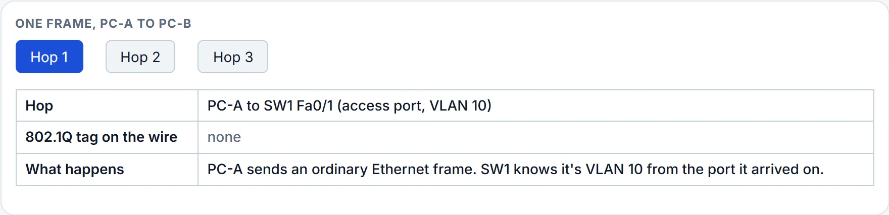
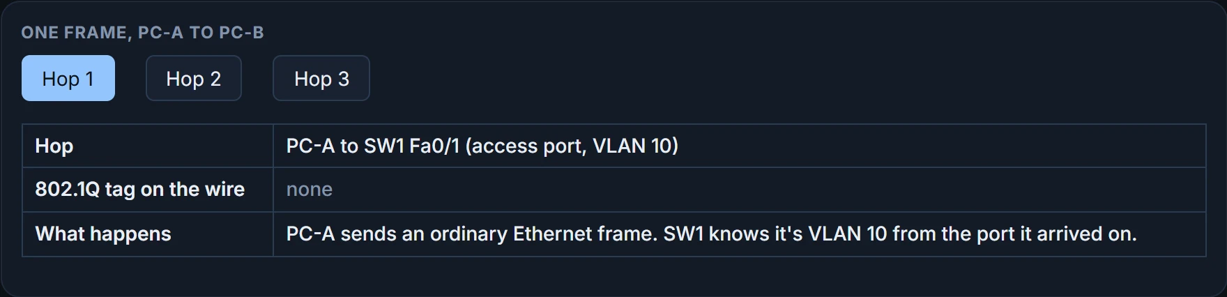
Tagged with VLAN 10, on the trunk only. SW1 adds the 802.1Q header as the frame leaves on Po1, and SW2 removes it before PC-B's port. Not every frame on a trunk carries a tag, though: frames in the native VLAN cross untagged. In this lab no user sends in VLAN 99, so every user frame on Po1 is tagged. At hop 3, the two MAC tables show it: each switch learns the far PC on Po1, not on one member cable, and each table is per VLAN.
You can think of the trunk as a covered bridge between two buildings, carrying parcels labelled with a floor number; each parcel is delivered to the same floor on the other side. (Where it stops: the native VLAN's parcels cross with no label, and land on whatever floor the far side calls native, which is why both ends must agree.)
The cable needs a floor number in the middle; the desk at the end hands you the parcel without the tag.
Continue the lesson
The whole lesson, with its drawings and its questions. 3 more sections after the ones above.