
IPv4 Addressing and Subnetting Lab
A hands-on CCNA subnetting lab. One /23 must serve four groups of different sizes. Size each request with the smallest block whose usable addresses cover it, place them biggest first, each at a start that is a multiple of its size so nothing overlaps, then give the router the first usable address on each LAN.
By Arif, founder of Daveth · Updated
The full 9 min walkthrough is in Daveth Pro (Network). See what the plan opens
What this page answers
How do you subnet a block with VLSM?
Size each request with the smallest block whose usable addresses, the block minus its subnet ID and broadcast, cover it. Then place them biggest first, each at the next start that is a multiple of its size, so no two overlap. Read it in “Place them without overlap”
The request
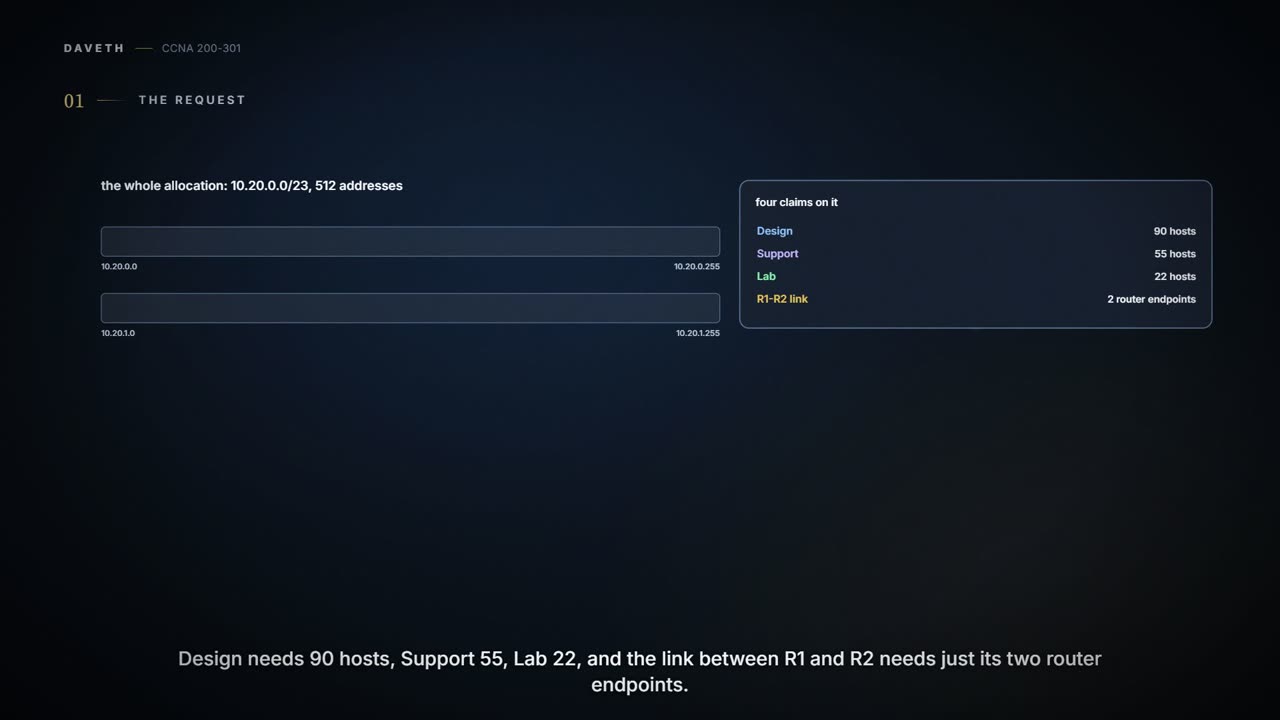
A lab page where the work is on paper first, then on a router. The outputs follow the command line used throughout this course. A school has been given one block, 10.20.0.0/23: 512 addresses, 10.20.0.0 to 10.20.1.255. Four groups want a share. (These are private addresses chosen for the lab, not anyone's real plan.)
| Who | Addresses needed |
|---|---|
| Design | 90 hosts |
| Support | 55 hosts |
| Lab | 22 hosts |
| R1-R2 link | 2 router endpoints |
Design, the biggest. Blocks must start on a multiple of their own size, so big blocks need big aligned gaps. Place them first, while the space is still in one piece, and the small ones fit into what's left.
The address cupboard has enough shelves. The trick is not putting a 90-person team in a 30-seat room.
Size each block
For each request, find the smallest block whose usable addresses cover it. Every block in this lab, /30 and larger, has two addresses hosts can't use: the first is the subnet ID and the last is the broadcast. So a block of 2 to the power of (32 minus the prefix) holds that many addresses, minus 2 for hosts.
| Who | Needs | Prefix | Addresses in the block | Usable for hosts |
|---|---|---|---|---|
| Design | 90 | /25 | 128 | 126 |
| Support | 55 | /26 | 64 | 62 |
| Lab | 22 | /27 | 32 | 30 |
| R1-R2 link | 2 | /30 | 4 | 2 |
/26 for Support: 64 addresses, 62 usable; a /27's 30 would be too few. The link's two router endpoints fit in a /30, with 4 addresses and 2 usable. (Some point-to-point links can use a /31 instead; this lab practises the ordinary /30 arithmetic.)
Place them without overlap
Now lay them on the /23, biggest first, each at the next start that's a multiple of its size. Design takes 10.20.0.0/25, the first 128. Support's /26 needs a start that's a multiple of 64. Here is the first candidate, 10.20.0.64:
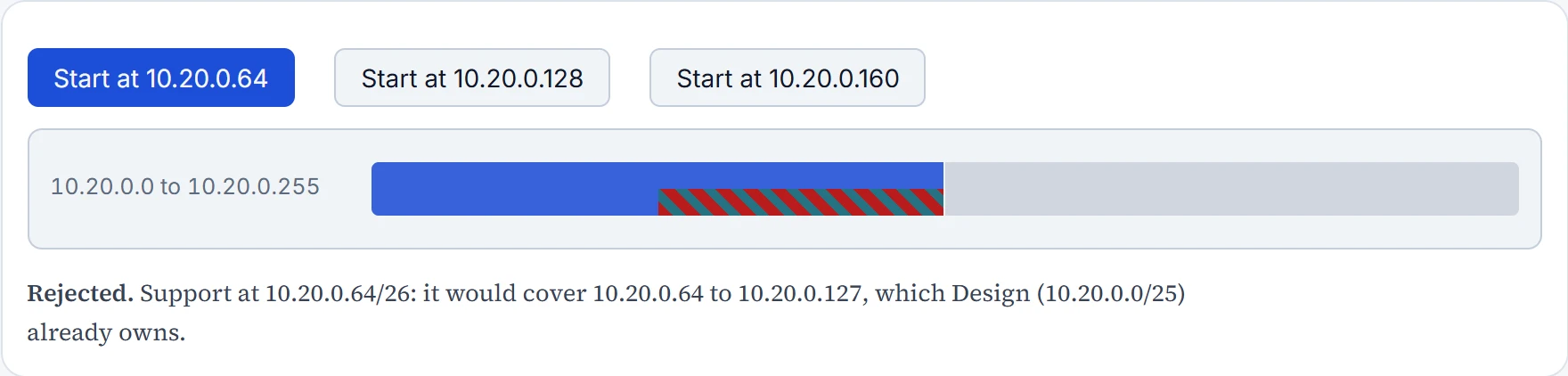
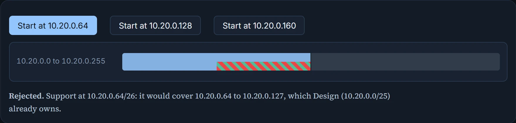
.64 would put Support's floor inside Design's: every address from .64 to .127 is already Design's, so that's a full collision, not a near miss. Judge overlap by the full range of each block, never by the subnet IDs alone. .160 isn't a multiple of 64 at all, so no /26 can start there. .128 is the one: aligned, and clear of Design.
The label says Support, but every desk on its floor is already Design's.
.192: Support ends at .191, and .192 is a multiple of 32. The link's /30 then goes at .224, the next multiple of 4 after Lab ends at .223. Everything sits inside 10.20.0.0 to 10.20.0.227, and the rest of the /23 stays free for later. The strip draws every block to scale, so a /30 really is a sliver next to a /25.
10.20.0.0/23: 512 addresses, drawn to scale (grey is free)
- Design: 10.20.0.0/25, 128 addresses
- Support: 10.20.0.128/26, 64 addresses
- Lab: 10.20.0.192/27, 32 addresses
- R1-R2 link: 10.20.0.224/30, 4 addresses
| Who | Subnet | Hosts | Broadcast | Usable |
|---|---|---|---|---|
| Design | 10.20.0.0/25 | 10.20.0.1 to 10.20.0.126 | 10.20.0.127 | 126 |
| Support | 10.20.0.128/26 | 10.20.0.129 to 10.20.0.190 | 10.20.0.191 | 62 |
| Lab | 10.20.0.192/27 | 10.20.0.193 to 10.20.0.222 | 10.20.0.223 | 30 |
| R1-R2 link | 10.20.0.224/30 | 10.20.0.225 to 10.20.0.226 | 10.20.0.227 | 2 |
Give R1 the gateways
R1 gets the first usable address on each LAN, and each PC gets an address in its own subnet, with R1's address there as its gateway: PC-D 10.20.0.126/25 via .1, PC-S 10.20.0.130/26 via .129, PC-L 10.20.0.194/27 via .193. The link block, 10.20.0.224/30, is planned here but not configured. On the router, only the router-facing addresses are typed; each PC's settings go in its own network settings.
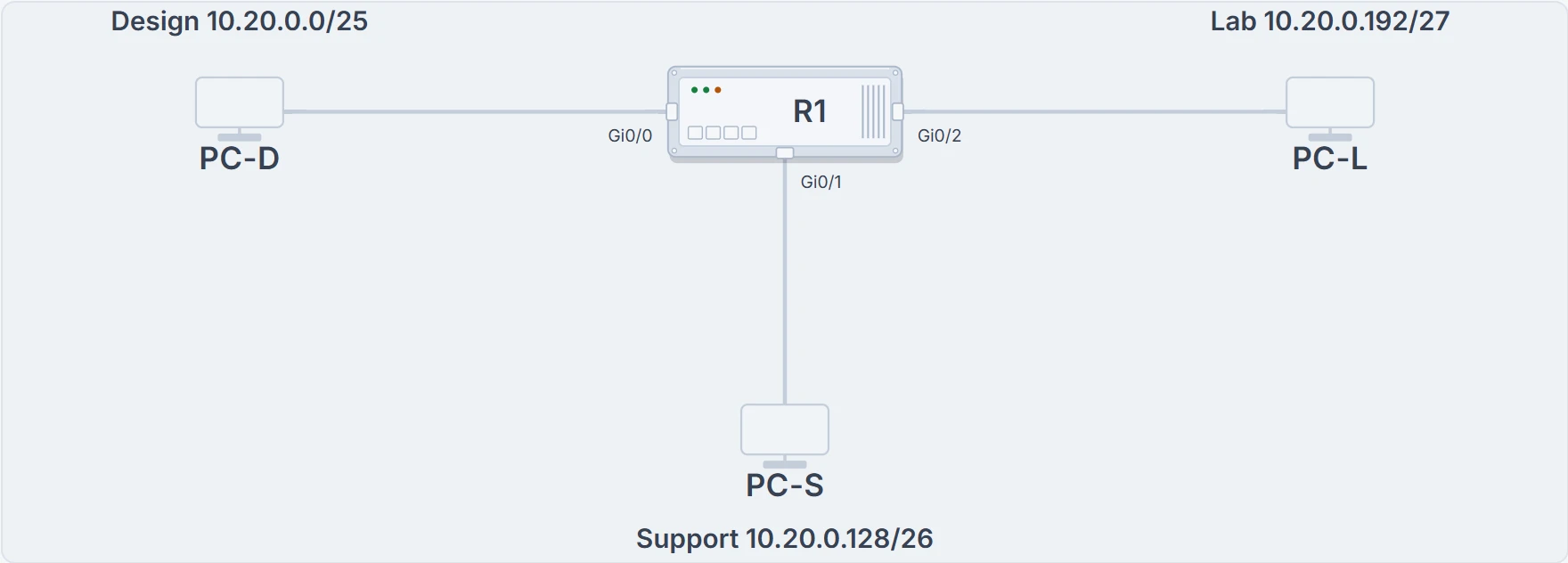
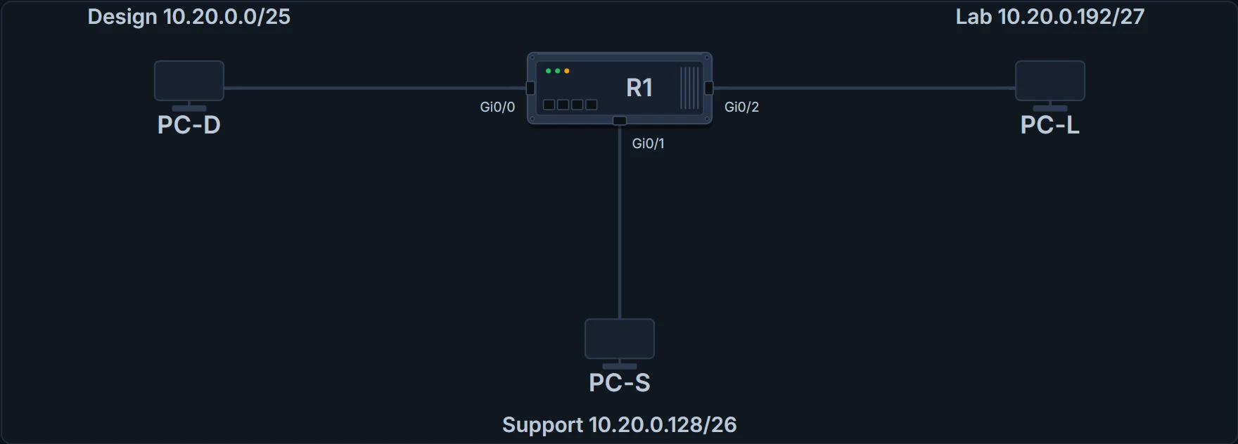
R1 and its three LANs, one test PC on each.
R1> enable
R1# configure terminal
Enter configuration commands, one per line.  End with CNTL/Z.
R1(config)# interface GigabitEthernet0/0
R1(config-if)# description Design-gateway
R1(config-if)# ip address 10.20.0.1 255.255.255.128
R1(config-if)# no shutdown
! (status messages omitted: the interface coming up)
R1(config-if)# interface GigabitEthernet0/1
R1(config-if)# description Support-gateway
R1(config-if)# ip address 10.20.0.129 255.255.255.192
R1(config-if)# no shutdown
! (status messages omitted: the interface coming up)
R1(config-if)# interface GigabitEthernet0/2
R1(config-if)# description Lab-gateway
R1(config-if)# ip address 10.20.0.193 255.255.255.224
R1(config-if)# no shutdown
! (status messages omitted: the interface coming up)
R1(config-if)# end
R1# show ip interface brief
Interface                  IP-Address      OK? Method Status                Protocol
GigabitEthernet0/0         10.20.0.1       YES manual up                    up
GigabitEthernet0/1         10.20.0.129     YES manual up                    up
GigabitEthernet0/2         10.20.0.193     YES manual up                    up
! (unused interfaces omitted)
R1# show ip route
Codes: L - local, C - connected, S - static, R - RIP, M - mobile, B - BGP
! (the rest of the legend of codes omitted)

Gateway of last resort is not set

      10.0.0.0/8 is variably subnetted, 6 subnets, 4 masks
C        10.20.0.0/25 is directly connected, GigabitEthernet0/0
L        10.20.0.1/32 is directly connected, GigabitEthernet0/0
C        10.20.0.128/26 is directly connected, GigabitEthernet0/1
L        10.20.0.129/32 is directly connected, GigabitEthernet0/1
C        10.20.0.192/27 is directly connected, GigabitEthernet0/2
L        10.20.0.193/32 is directly connected, GigabitEthernet0/2
Each connected route, the C lines, appears only because its interface is up/up with an address; the L lines are R1's own addresses. show running-config would show the same addresses, but it proves only what was typed, not that the interface is working. Then test in order: from PC-D, ping its gateway, 10.20.0.1; then PC-S, 10.20.0.130, once both ends and both gateways are up. A reply proves this path and its reply, not a policy for everything else.
Continue the lesson
The whole lesson, with its drawings and its questions. The rest of this section and 3 more after it.