
Multiple Spanning Tree
One spanning tree for every VLAN cannot share load; one tree per VLAN costs a BPDU per VLAN on every link. MST maps many VLANs onto a few instances, so three trees can serve thousands of VLANs, and only one BPDU, the IST's, crosses each link. Switches form one region only when their name, revision and VLAN-to-instance map all match.
By Arif, founder of Daveth · Updated
The full 9 min walkthrough is in Daveth Pro (Network). See what the plan opens
What this page answers
What is Multiple Spanning Tree (MST)?
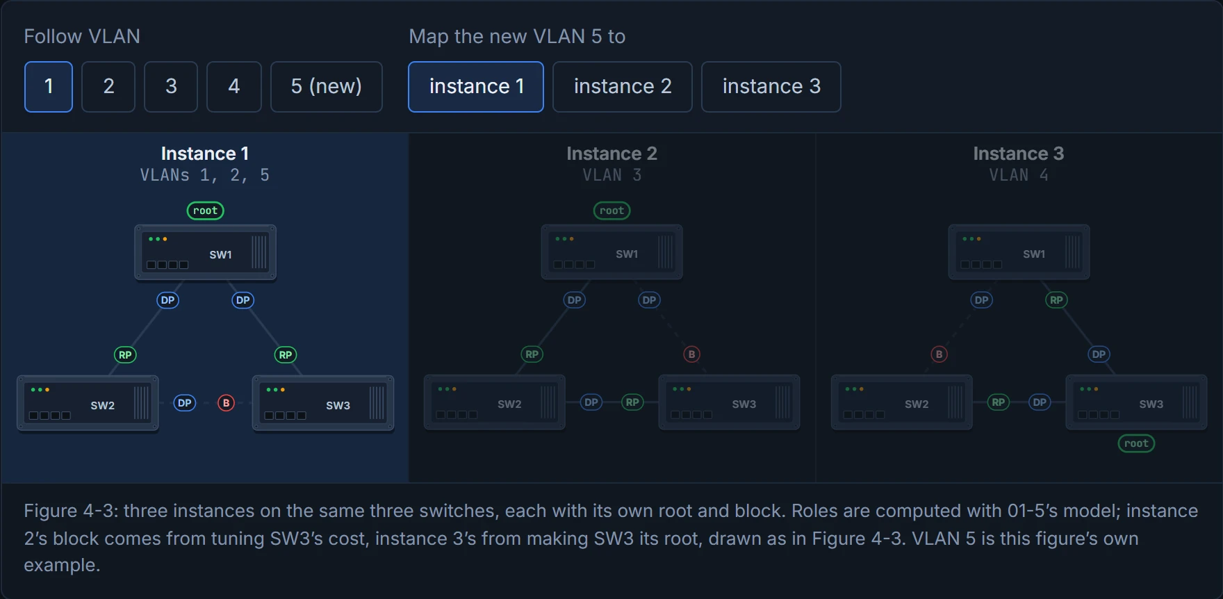
A spanning tree mode that maps VLANs to a few instances, each with its own topology. In the guide's example VLANs 1 and 2 share one instance, VLAN 3 has a second and VLAN 4 a third: three topologies for four VLANs, and still three if ten more VLANs join. Read it in “4.1 One tree for everyone, or one tree each?”
How do you configure an MST region?
spanning-tree mode mst, then in spanning-tree mst configuration set the name, the revision and each instance's VLANs with instance n vlan list. Same name, same revision and same map on every switch make one region; show spanning-tree mst configuration proves it. Read it in the lesson
4.1 One tree for everyone, or one tree each?
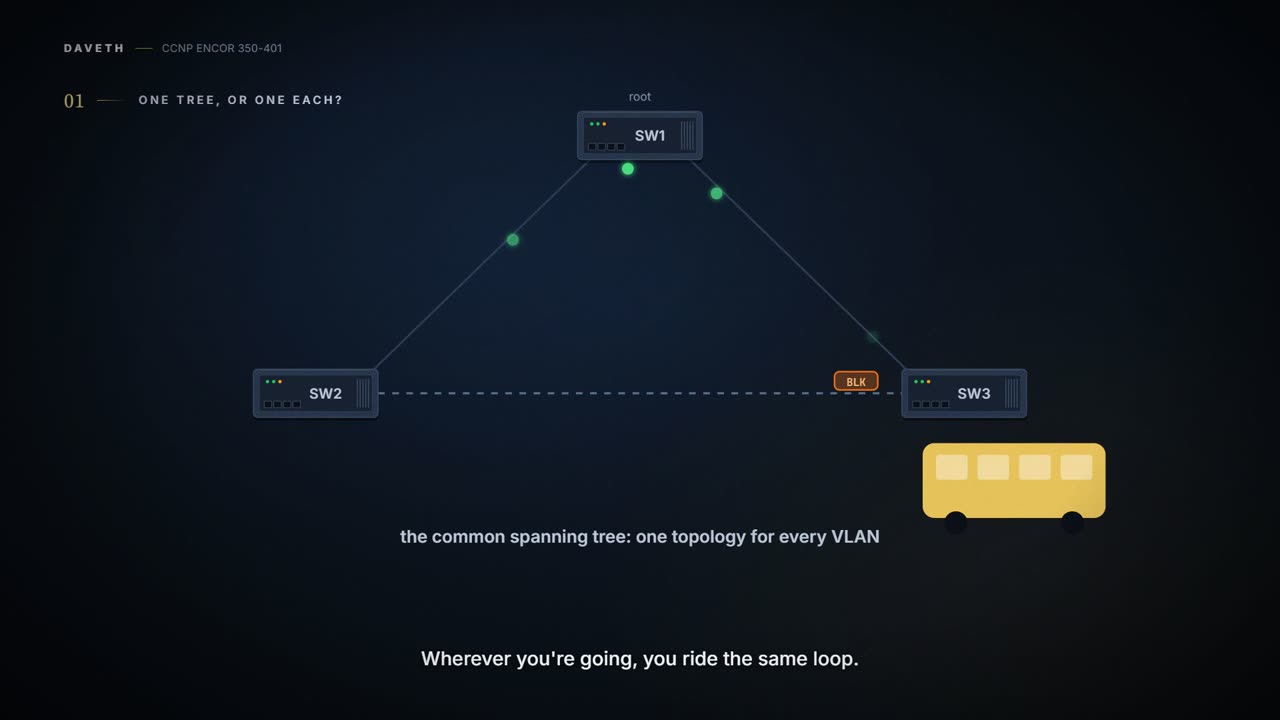
The original 802.1D ran one spanning tree for the whole network, and so did 802.1Q: the Common Spanning Tree (CST). Every VLAN shared one topology, so you couldn't block VLAN 10 on one link and VLAN 20 on another to share the load. The guide's example (its Figure 4-1) is a triangle with SW1 as root: all traffic from SW2 to SW3 crosses SW1. If VLAN 4 lives only on SW2 and SW3, too bad: it still goes the long way round. It's basically like a town with one bus route: whoever you are and wherever you're going, you ride the same loop.
Cisco's answer was PVST: one tree per VLAN, so each VLAN can have its own root and its own costs. Add ten VLANs to four and the switches run fourteen trees. In the guide's per-VLAN version (its Figure 4-2), VLAN 3's block moves to the SW1–SW3 link to suit servers on SW2 and clients on SW3, and VLAN 4's moves to SW2–SW1 so its traffic runs direct. D1 below counts what that flexibility costs.
Now picture yourself with thousands of VLANs. Every switch sends and processes BPDUs for every one, and when a big trunk fails, it recomputes every tree at once. That's a real load on the switch's CPU. You can think of it as giving every member of a family their own car: perfectly flexible, and the driveway is full.
D1
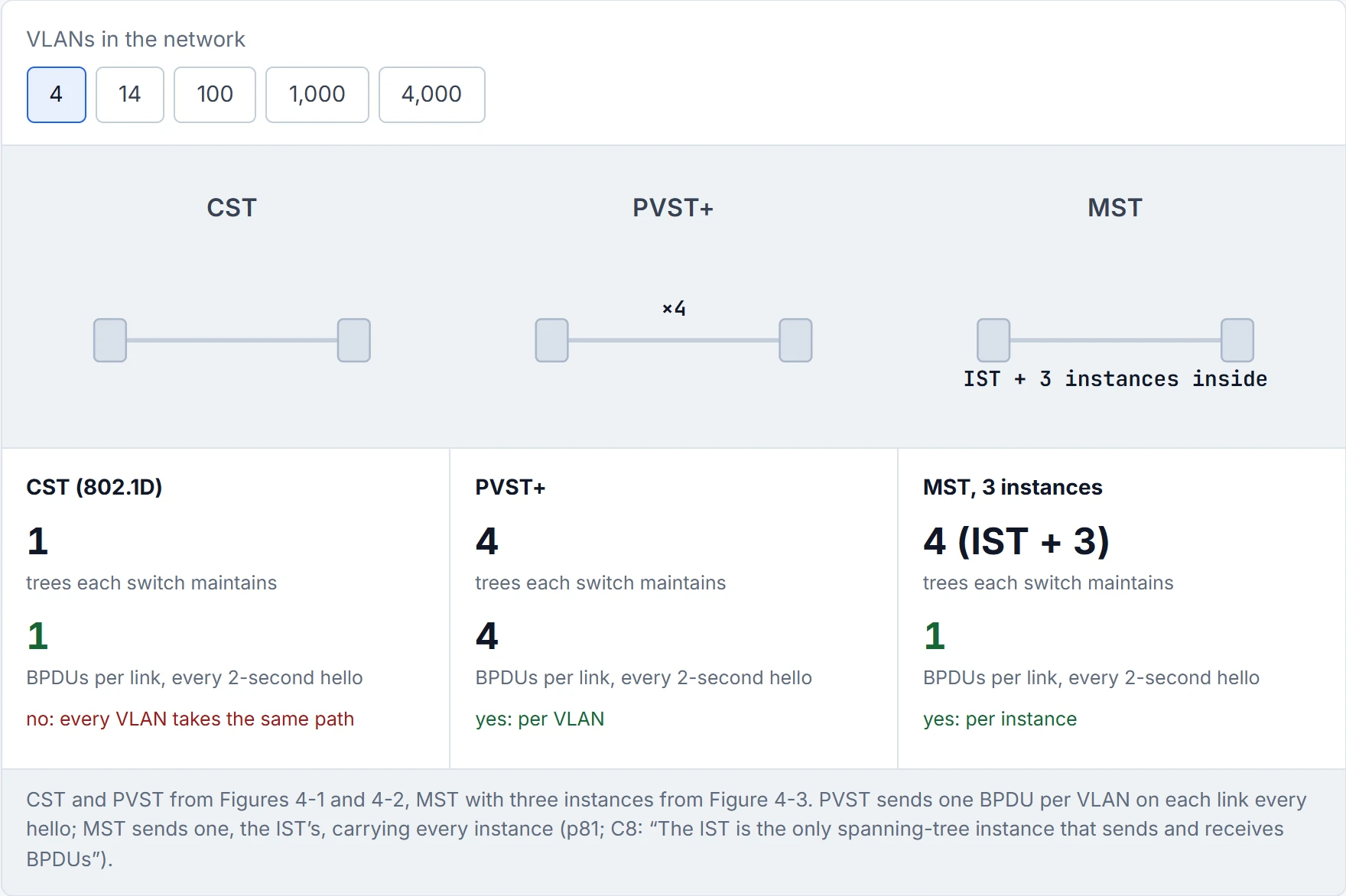
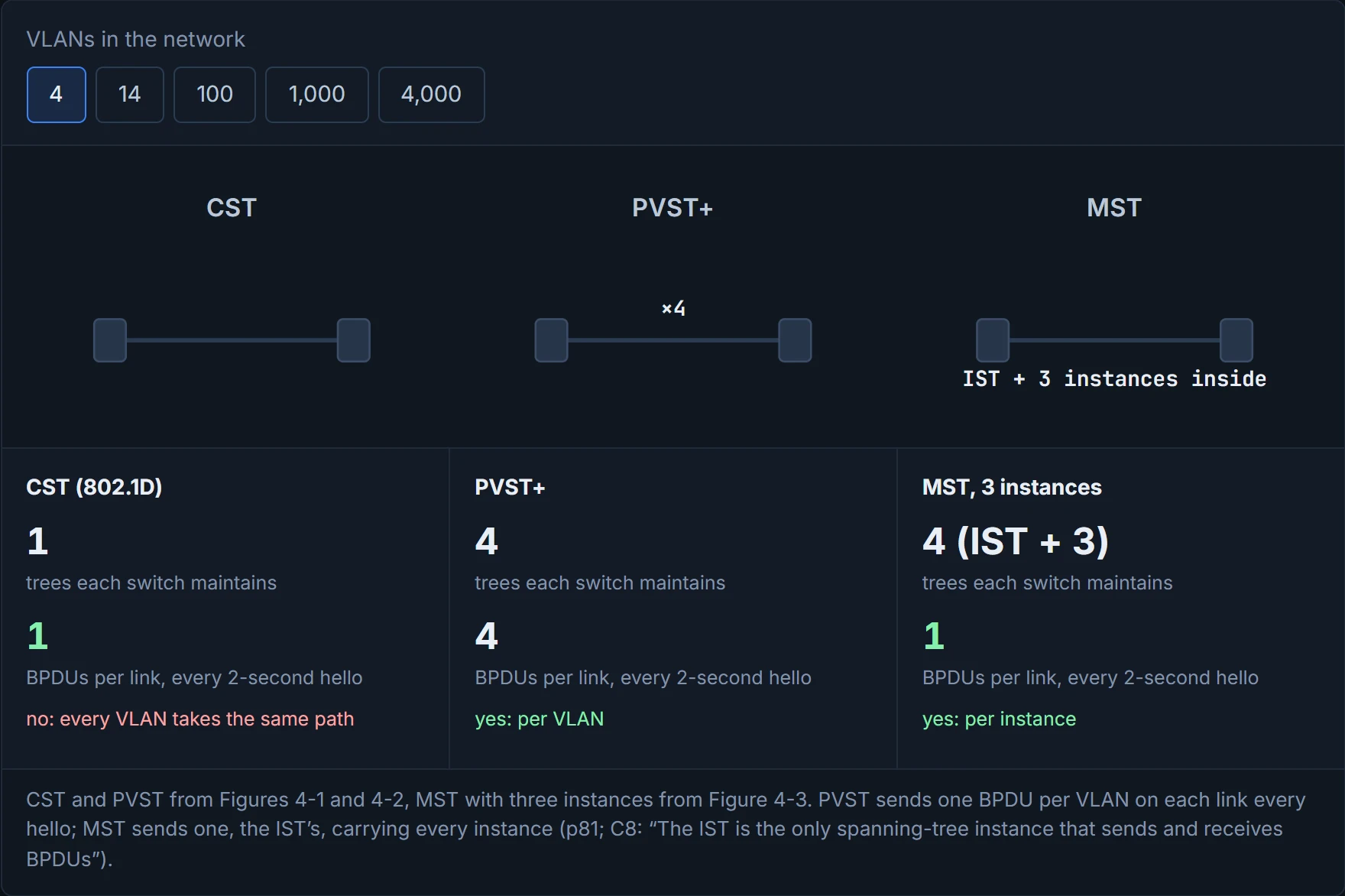
PVST scales beautifully, right up until someone creates their thousandth VLAN. Then the CPU starts writing its resignation letter.
MST takes the middle road. You build a small number of trees, and map one or more VLANs onto each one. Each tree is an MST instance (MSTI). In a way, it's just carpooling for VLANs: the ones going the same way share a car.
In Figure 4-3, VLANs 1 and 2 share one instance, VLAN 3 has a second and VLAN 4 a third: three topologies for four VLANs. Add ten more VLANs to those instances and it's still three trees. (Three MSTIs, that is: underneath them the IST, instance 0, always runs as well, section 4.3.) Think about the last time you sorted washing: you don't run a separate cycle for every sock. Whites in one load, darks in another, delicates in a third. Three loads, however many clothes.
D2
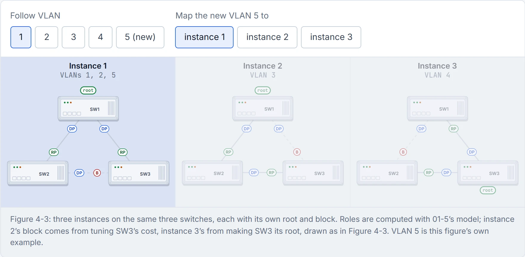
MST is what happens when spanning tree discovers the concept of "batch processing" forty years after everyone else.
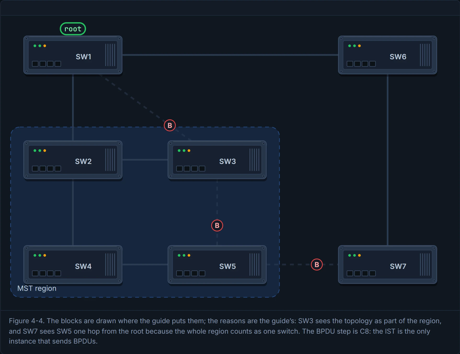
A group of MST switches with the same high-level configuration is an MST region. To switches outside it, the whole region looks like one big virtual switch. Figure 4-4 shows the odd results that follow. SW3 blocks its port to SW1, a port that would normally be a root port, because it sees the topology as part of the collective. And SW7, outside, blocks its port towards the region. Look at the SW5–SW7 link: SW5 is two physical hops from the root, but the region counts as one switch, so SW5 advertises one hop, fewer than SW7's two. SW5's end is designated and SW7's end blocks. (Inside the region, SW5 also has an ordinary block towards SW3, from the usual tie-breakers of 01-5.) The region also looks like one switch for a reason: compatibility with the switches outside it. It acts kind of like a building seen from the street: you see one address, however many rooms are inside.
Under every region runs a special instance, the internal spanning tree (IST), which is always instance 0. It runs on every port of every switch in the region, whatever VLANs those ports carry. The other instances' information rides inside the IST's BPDU, so the region sends one set of BPDUs, however many instances it has. Cisco: the IST "is the only spanning-tree instance that sends and receives BPDUs". That's roughly equivalent to one envelope with several letters inside, instead of a postman per letter.
How many instances? The guide says Cisco supports 16 by default, 0 to 15. That's out of date for current platforms: on a Catalyst 9300 at 17.9, the switch stack supports up to 65 MST instances, numbered anywhere from 0 to 4094.
D3
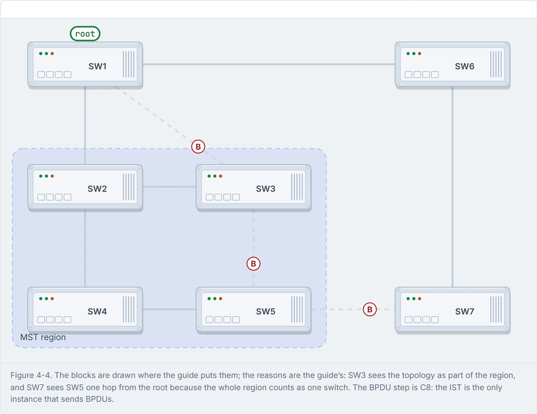
Step 1 of 4 The real topology (Figure 4-4). SW2 to SW5 form an MST region. SW3 blocks its port towards SW1, a port that would normally be its root port, because it sees the topology as part of the region.
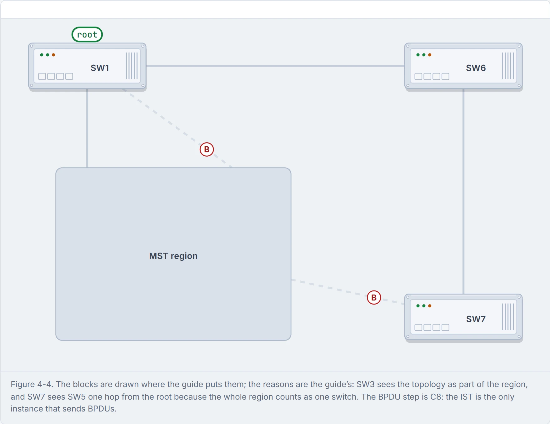
Step 2 of 4 What the switches outside see: one big switch. The two links from SW1 into the region are two links to the same switch, and one of them blocks.
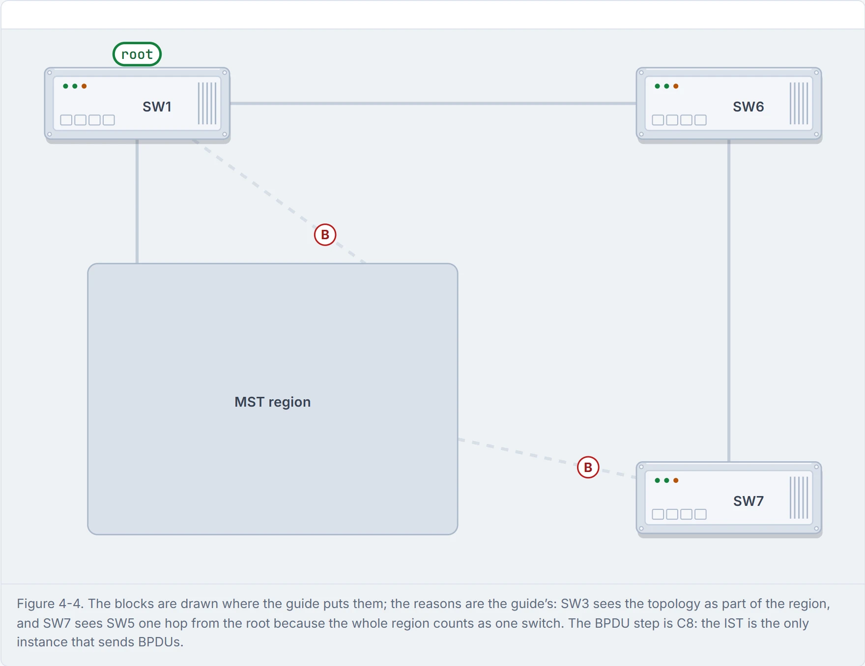
Step 3 of 4 That’s why SW7 blocks towards the region. Look at the SW5–SW7 link itself: SW5 is two physical hops from the root, but the region counts as one switch, so SW5 advertises one hop, fewer than SW7’s two. SW5’s end is designated, and SW7’s end blocks.
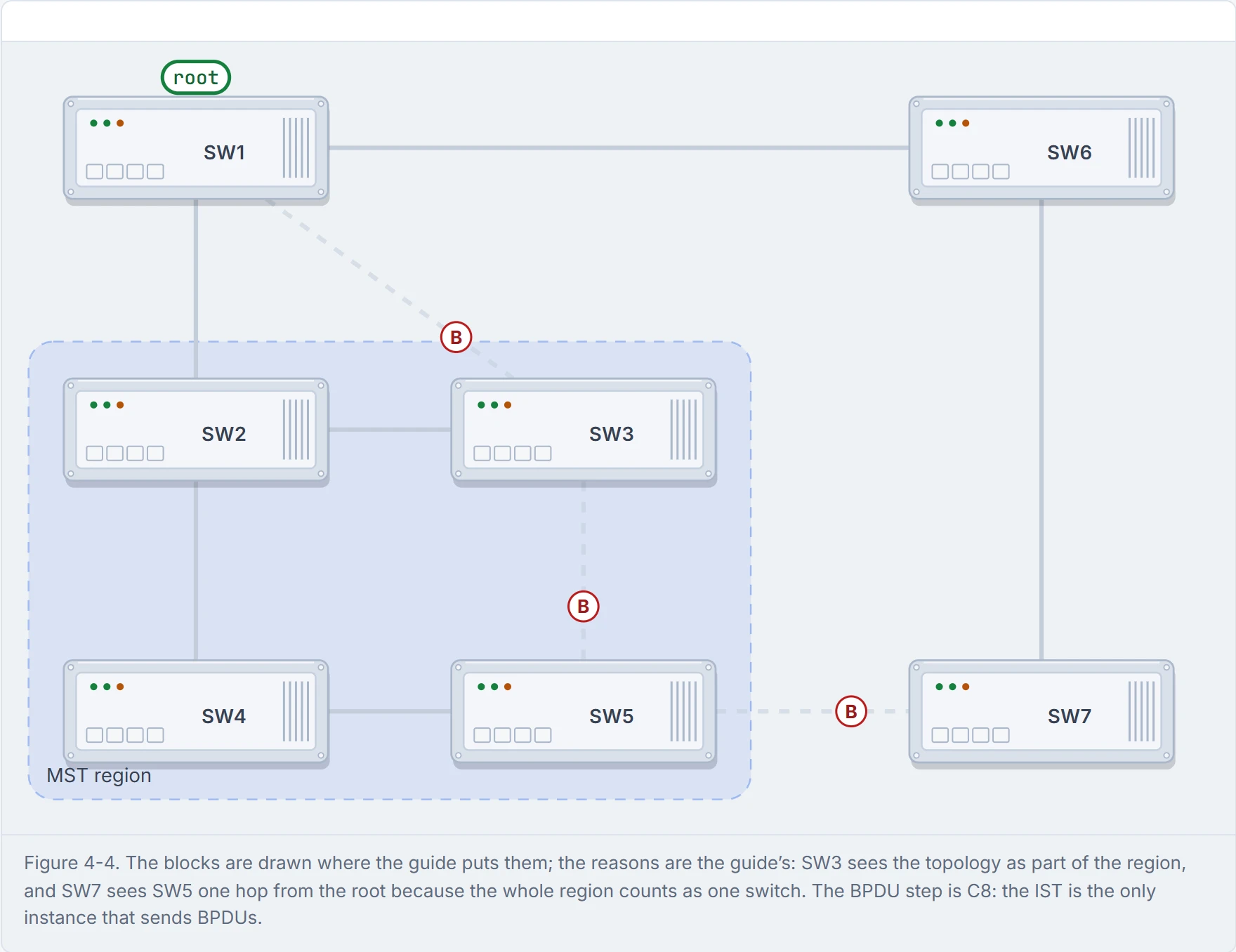
Step 4 of 4 Inside the region, each link carries one BPDU per hello: the IST’s, instance 0, with every other instance’s information nested inside it. However many instances, one set of BPDUs.
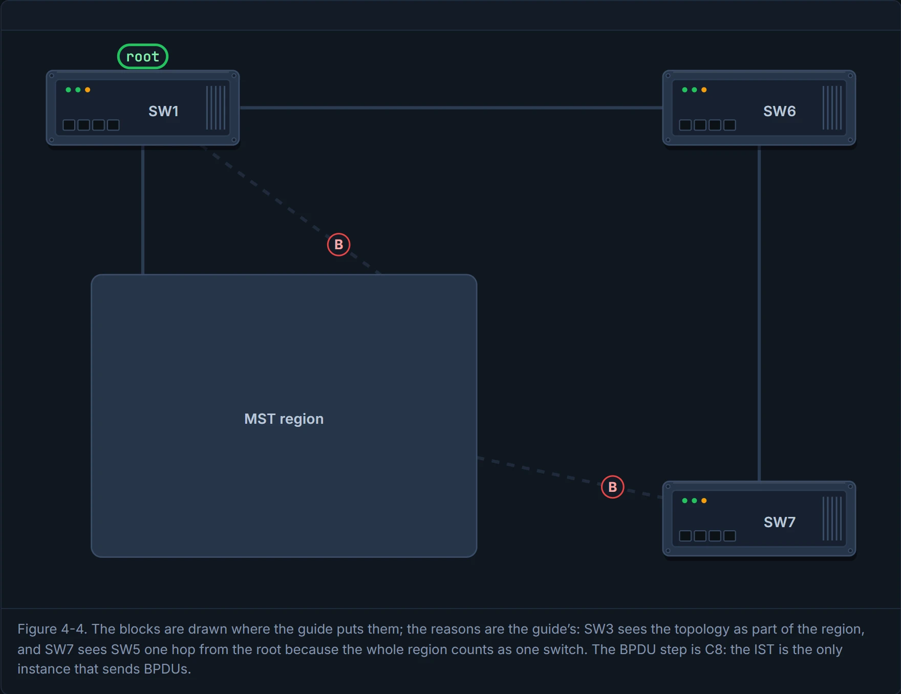
From outside, an MST region is the world's largest switch. It just happens to have several power cords.
The guide's steps:
SW1(config)# spanning-tree mode mst
SW1(config)# spanning-tree mst 0 root primary
SW1(config)# spanning-tree mst 1 root primary
SW1(config)# spanning-tree mst 2 root primary
SW1(config)# spanning-tree mst configuration
SW1(config-mst)# name ENTERPRISE_CORE
SW1(config-mst)# revision 2
SW1(config-mst)# instance 1 vlan 10,20
SW1(config-mst)# instance 2 vlan 99
spanning-tree mode mstturns it on.- Optionally, place each instance's root:
spanning-tree mst <n> priority <p>, 0 to 61,440 in steps of 4,096, orspanning-tree mst <n> root primary|secondary, which set 24,576 and 28,672 (with the same optionaldiameterkeyword as 01-6). Same values as 01-6, per instance. - Map VLANs. Every VLAN starts in instance 0. Enter
spanning-tree mst configuration, theninstance <n> vlan <list>. Consider it your laundry basket: everything lands in instance 0 until you sort it into a load. revision <n>: it must be the same on every switch in the region. The guide also calls it the version number, which is the word quiz Q5 uses.- Optionally,
name <region>. The default name is an empty string.
Here's the part that trips people. Switches are in the same region only if all three match: the name, the revision number and the VLAN-to-instance map. If you've ever tried to join a video call with the wrong meeting code, it's the same: one digit out and you're in a different meeting. The two meetings can still pass notes through the building's front desk (a boundary, section 4.9), but you're not in the same room. And nobody distributes the map for you: the root doesn't advertise it. Each switch uses its own configuration, so every switch has to be typed identically (quiz Q4 and Q5).
D4
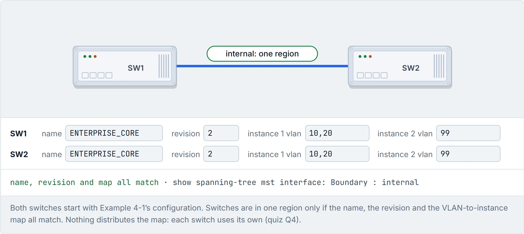
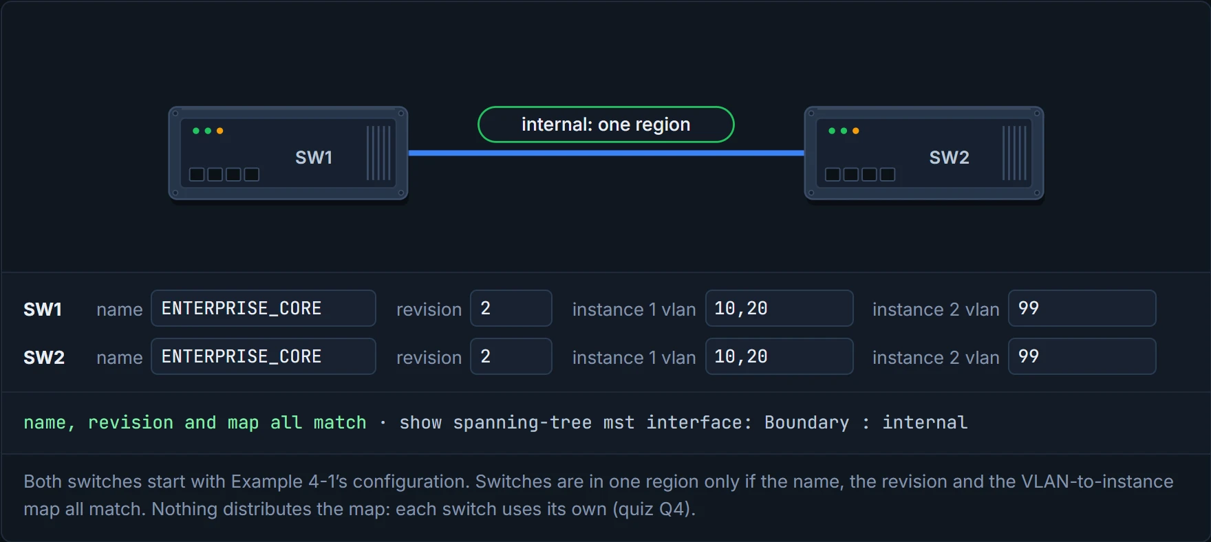
MST regions are a strict book club: same book, same edition, same chapter, or you're sitting at a different table.
show spanning-tree mst configuration is the quick check: the name, the revision, and each instance's VLANs. Instance 0 lists every VLAN you didn't map somewhere else, whether or not it exists on the switch: 1-9,11-19,21-98,100-4094. Compare it on two switches before anything else. It works behind the scenes just like comparing two copies of a contract line by line: the region only forms if they're identical.
Plain show spanning-tree now lists instances, MST0, MST1, MST2, not VLANs, and the bridge priority it shows is the switch priority plus the instance number: 24577 is 24,576 plus instance 1. You met the same arithmetic in 01-5, where it was the VLAN number.
show spanning-tree mst [n] puts the VLANs mapped next to each instance, which is much easier to troubleshoot from. show spanning-tree mst interface gi1/0/1 gives one port's role and state in every instance, plus whether it's an edge port, its link type, whether it's a region boundary, and its BPDU guard and filter settings.
Two things in that output the guide doesn't explain. The port costs are 20000: in MST mode the switch uses the long path-cost method, and 20,000 is the long cost of 1 Gbps (01-5's table). And there's a max hops 20: inside a region the root sends its BPDU with the hop count at the maximum, 20 by default, and each switch takes one off. It's like a message passed down a queue with "pass it on, 20 times at most" written on it.
vlans mapped: 1-9,11-19,21-98,100-4094 is the only line in networking that lists four thousand things and still manages to be the short version.
Everything 01-6 taught still works, just per instance. Port cost: spanning-tree mst <n> cost <c>. In Example 4-6, SW3's Gi1/0/1 goes to cost 1 in instance 0, and its Gi1/0/2 changes from Altn BLK to Desg FWD. Port priority: spanning-tree mst <n> port-priority <p>. In Example 4-7, SW4's Gi1/0/5 goes to 64 and shows 64.5 in the Prio.Nbr column. You can think of it as the same set of kitchen knobs, now labelled by burner.
So it's 01-6 with one extra word in every command. And that's the point: instance 1 can have its root on one core switch and instance 2 on the other, which is how MST gets back the load sharing that CST lost. Just like when you split the school run with a neighbour: you drive on Mondays, they drive on Tuesdays, and both cars earn their keep.
MST tuning is 01-6 wearing a name badge that says "instance 1".
The IST runs on every link in the region, whatever VLANs a link actually carries. So the IST can put a block somewhere you didn't expect. Picture yourself on a road where the council closes the only lane marked for buses, because it counted the car lanes and the bus lane as the same road.
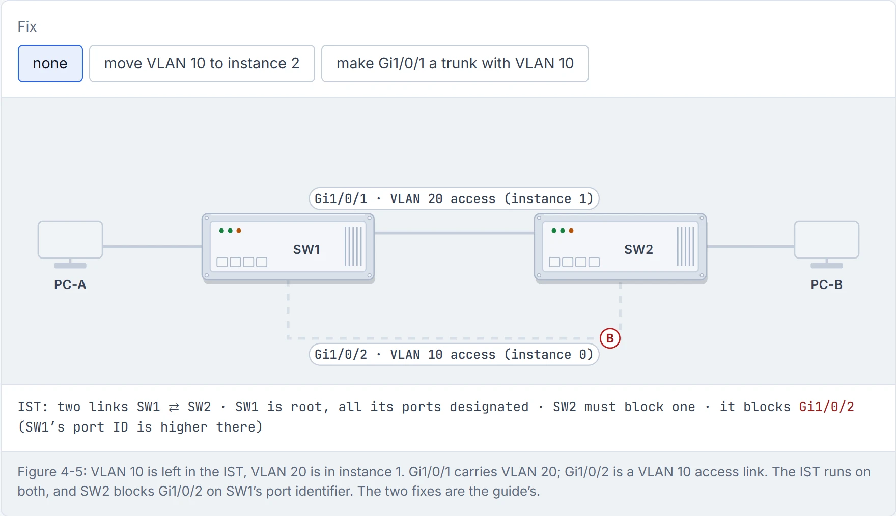
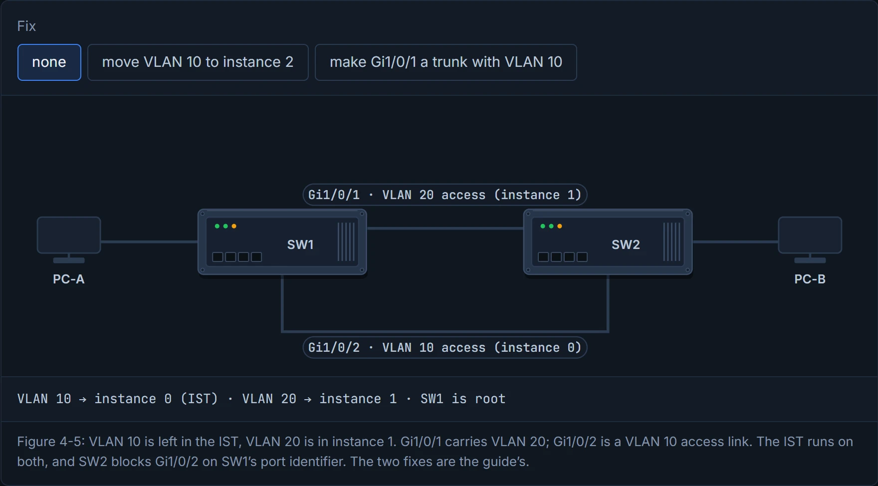
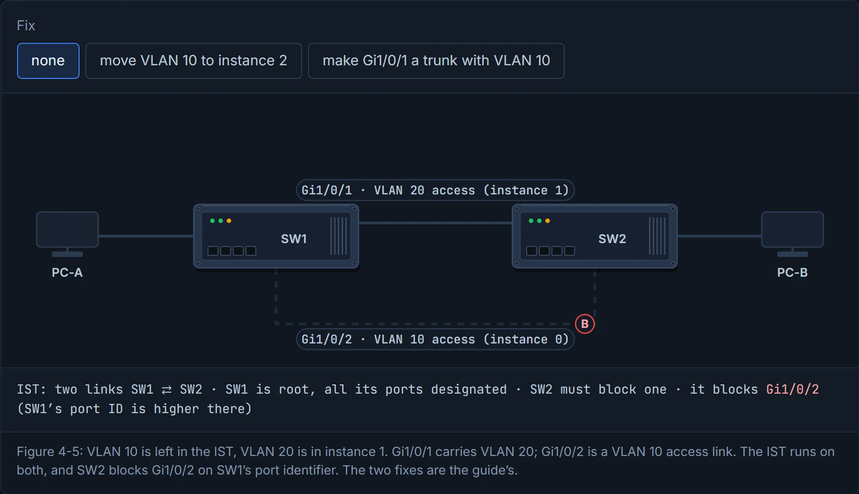
Figure 4-5: VLAN 10 is left in the IST; VLAN 20 is in instance 1. SW1 and SW2 have two links: Gi1/0/1 carries VLAN 20, and Gi1/0/2 is an access link in VLAN 10, where PC-A and PC-B talk. But for the IST, both links are just two links between the same two switches. SW1 is root, so SW2 must block one, and it blocks Gi1/0/2, on SW1's port identifier. That's the IST instance, which is the one VLAN 10 lives in. PC-A and PC-B are cut off. It's basically like a fire drill that locks the one door your office uses, because the plan was drawn for the whole building.
The two fixes:
- move VLAN 10 out of the IST into another instance, so its topology is built from the links that instance actually uses (Cisco's own write-up of this case calls this the preferred fix); or
- allow the IST's VLANs on every inter-switch trunk.
Why does the move work here, when section 4.8 will say an instance's tree ignores pruning? Because in Figure 4-5 both links are access ports, each in one VLAN: VLAN 10's instance is only on the port that carries VLAN 10. A trunk is in every instance, whatever you prune off it. The IST is the exception to both: it's on every port, access or trunk.
D5
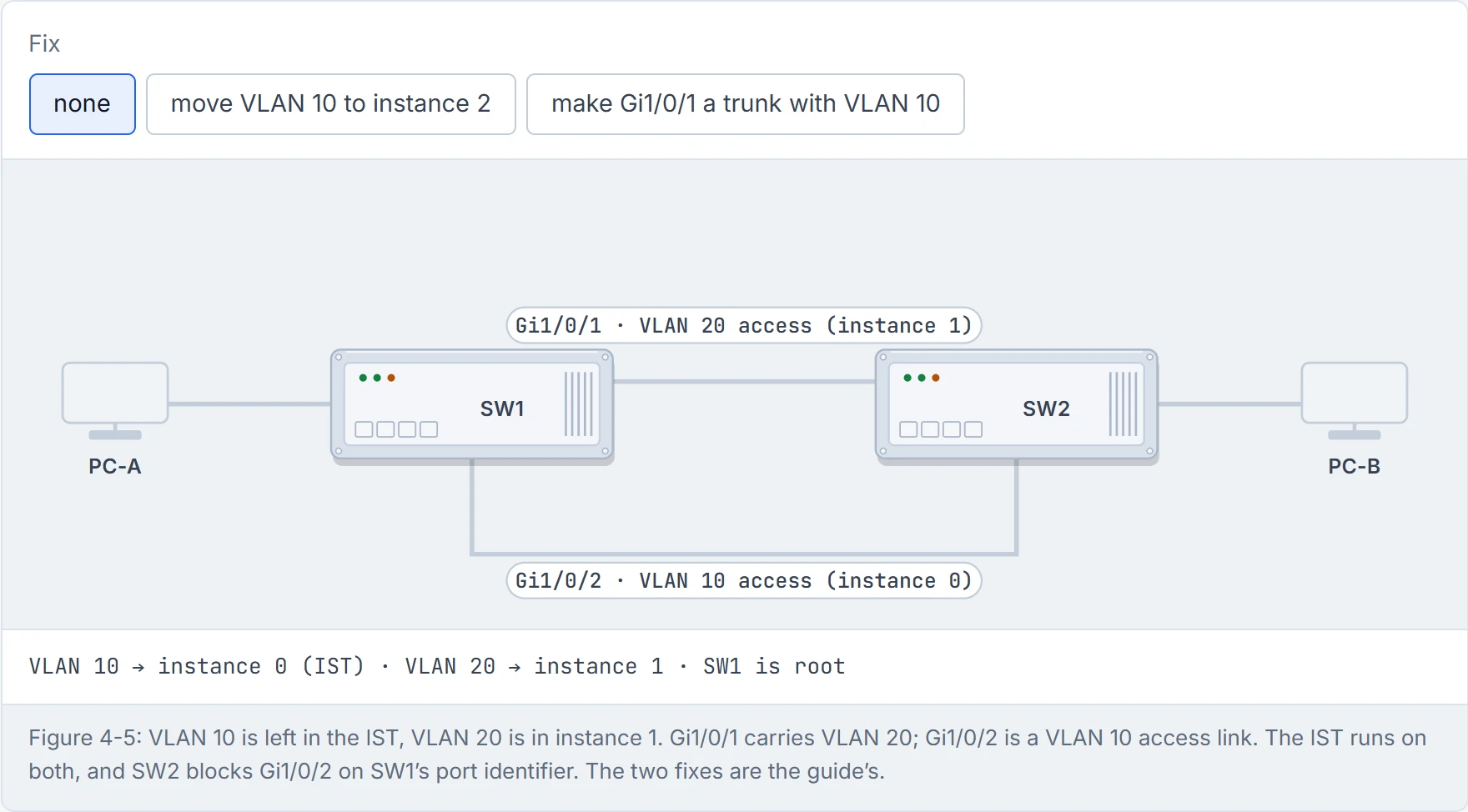
Step 1 of 3 PC-A and PC-B are both in VLAN 10, and there’s a VLAN 10 access link straight between their switches. Surely they can talk?
Step 2 of 3 The IST runs on both links, whatever VLANs they carry. To the IST they’re just two links to the same switch, so SW2 blocks one: Gi1/0/2, on SW1’s port identifier.
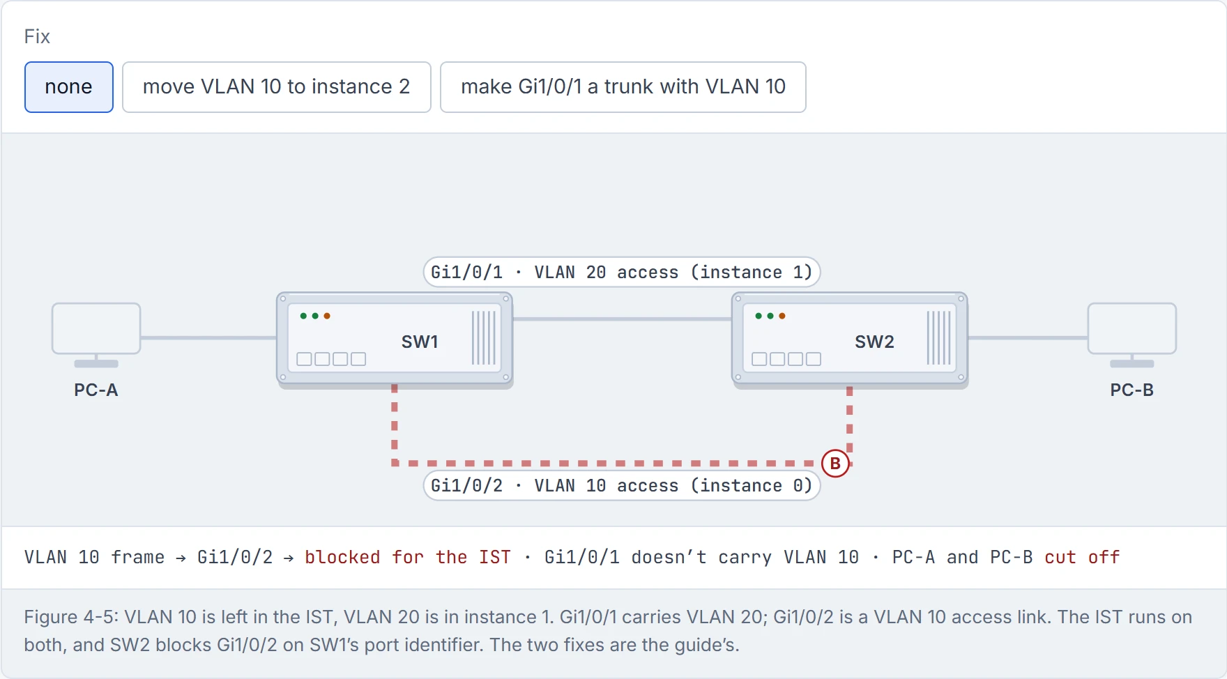
Step 3 of 3 VLAN 10 lives in the IST, and the IST has blocked the only link that carries VLAN 10. The frame dies at SW2. The block was placed by counting links, not VLANs.
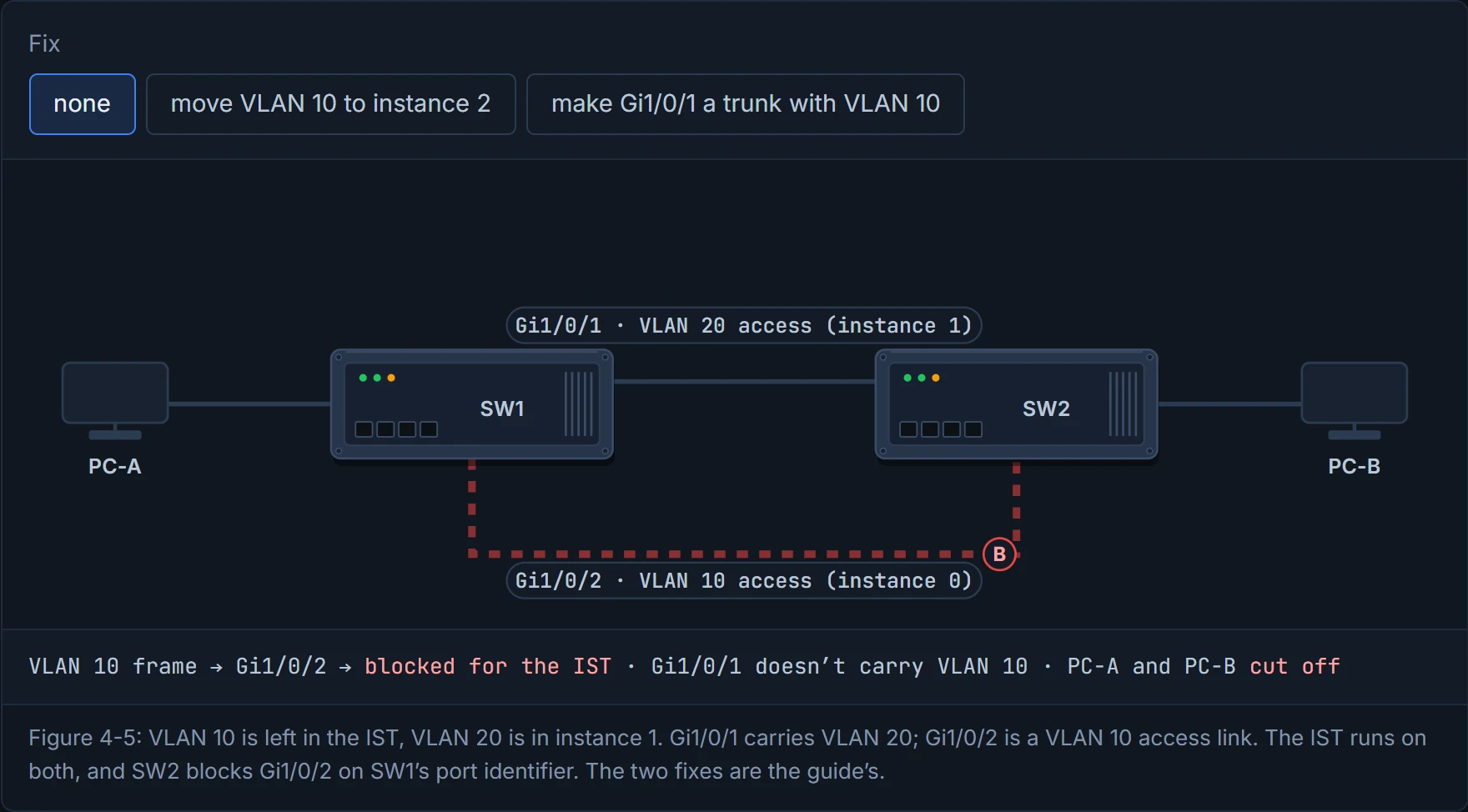
The IST doesn't care what's on a link. It's the one colleague who treats every meeting as mandatory.
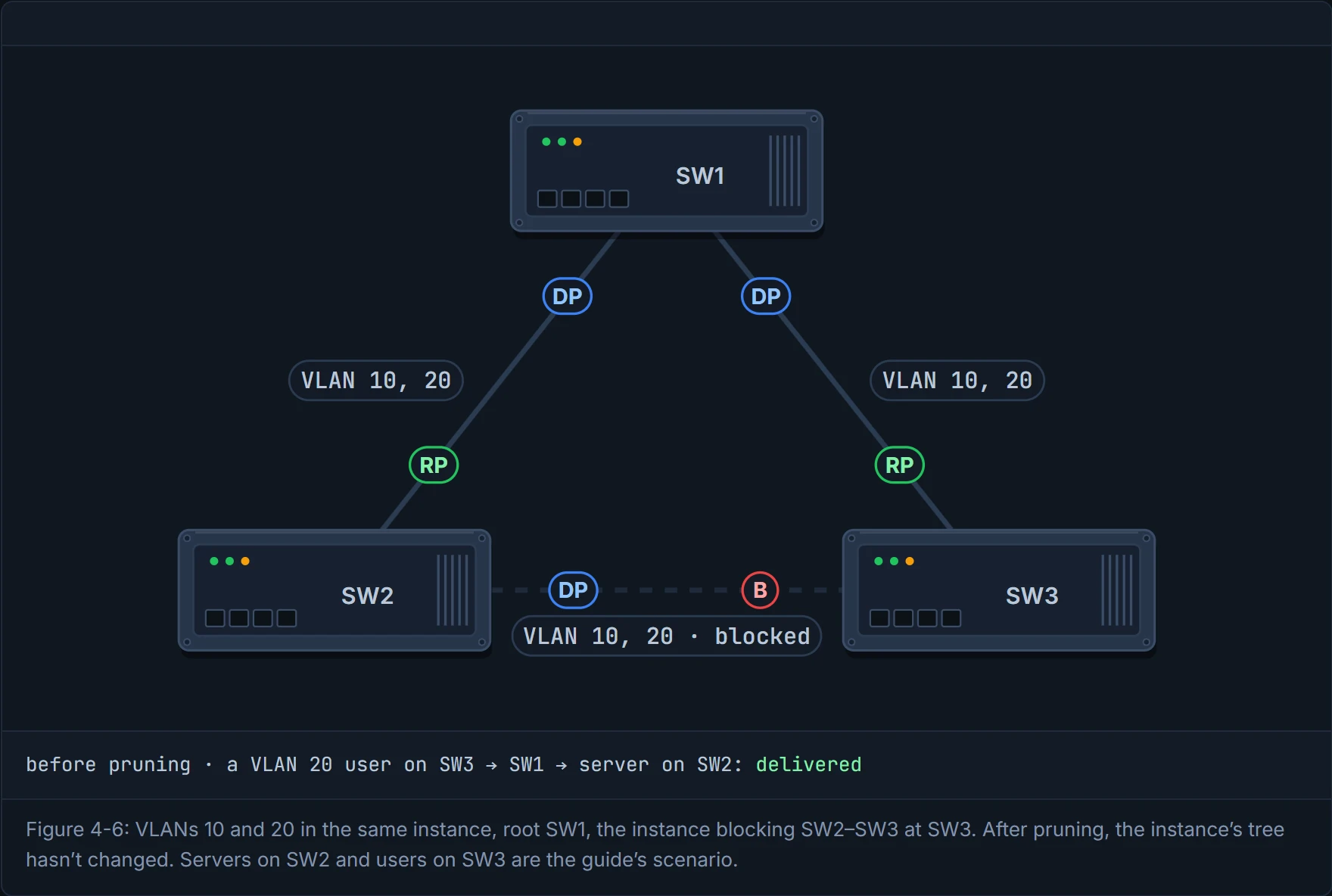
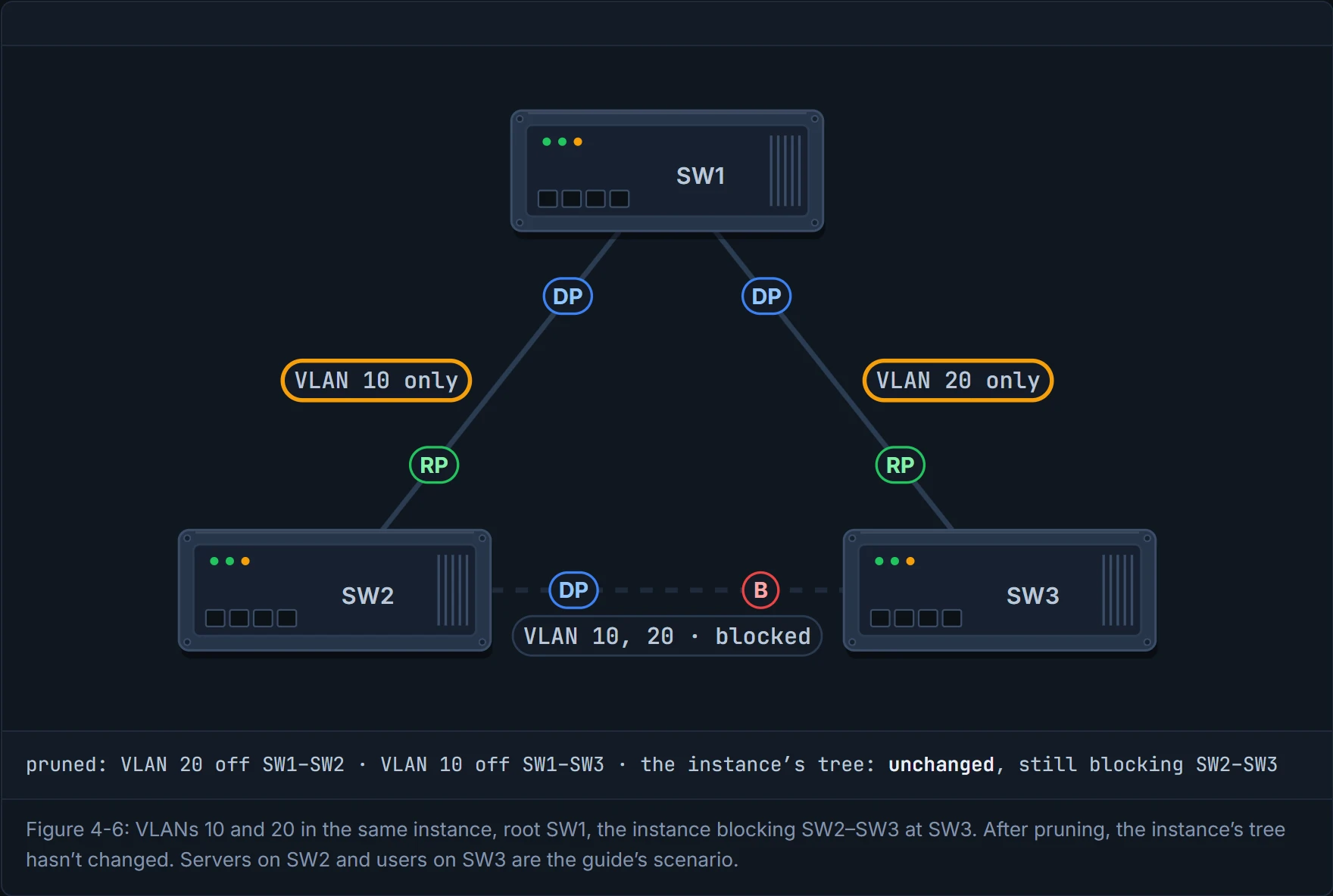
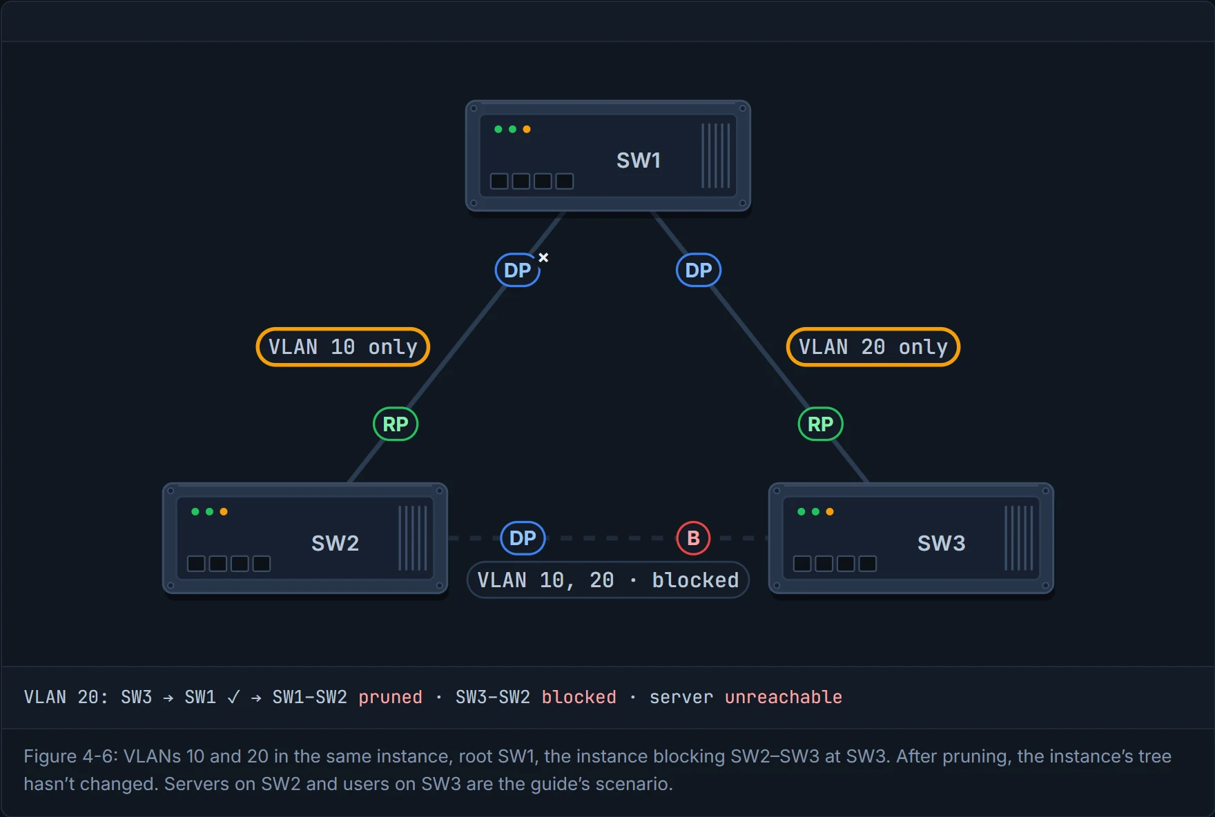
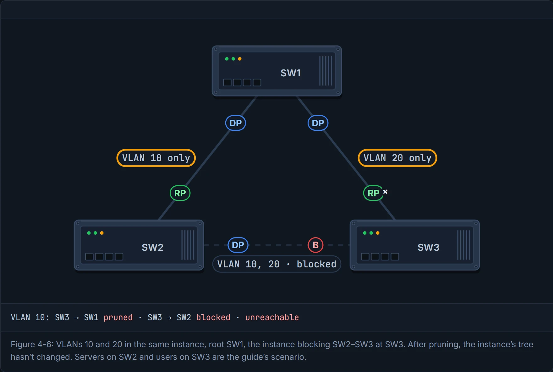
Pruning VLANs off trunks is a normal way to spread load. But with MST, VLANs that share an instance share one tree, and the tree doesn't know you pruned. Have you ever noticed how a satnav keeps routing you down a road that's just been closed? The tree is that satnav. In Figure 4-6, VLANs 10 and 20 run everywhere, in the same instance. A junior engineer prunes VLAN 20 from SW1–SW2 and VLAN 10 from SW1–SW3 to balance them. The instance still blocks SW2–SW3, so users on SW1 and SW3 can no longer reach the servers on SW2.
The guide's rule: prune all the VLANs of an instance together, or none. That's roughly equivalent to putting socks away in pairs: take one out on its own, and the drawer still thinks it holds a pair. Cisco's write-up says the same, and gives the reason: "the topology is determined by the instance, regardless of the VLANs mapped to it". A trunk stays in the instance's tree whatever you prune off it, so prune an instance's VLANs all together, from a link the instance won't need to forward on.
D6
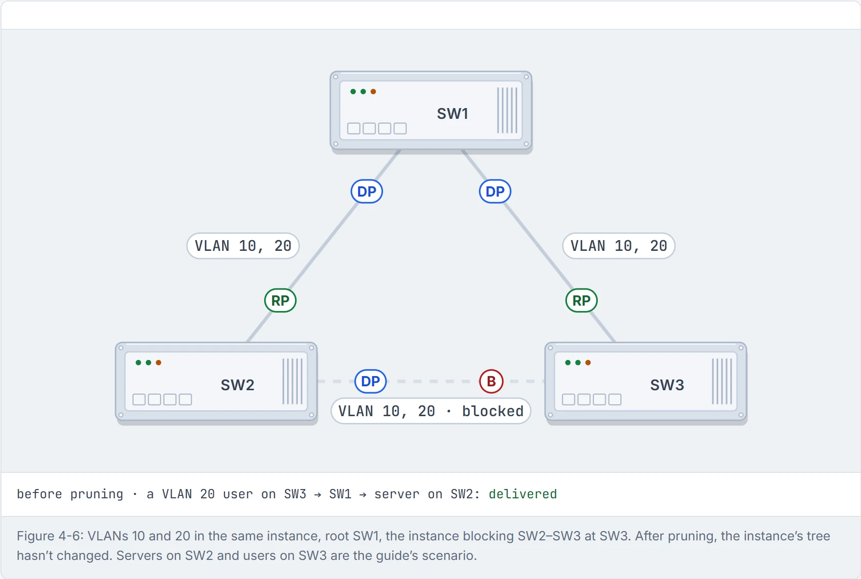
Step 1 of 4 Before: both VLANs run on every trunk. The instance blocks SW2–SW3, so a user on SW3 reaches the servers on SW2 through SW1.
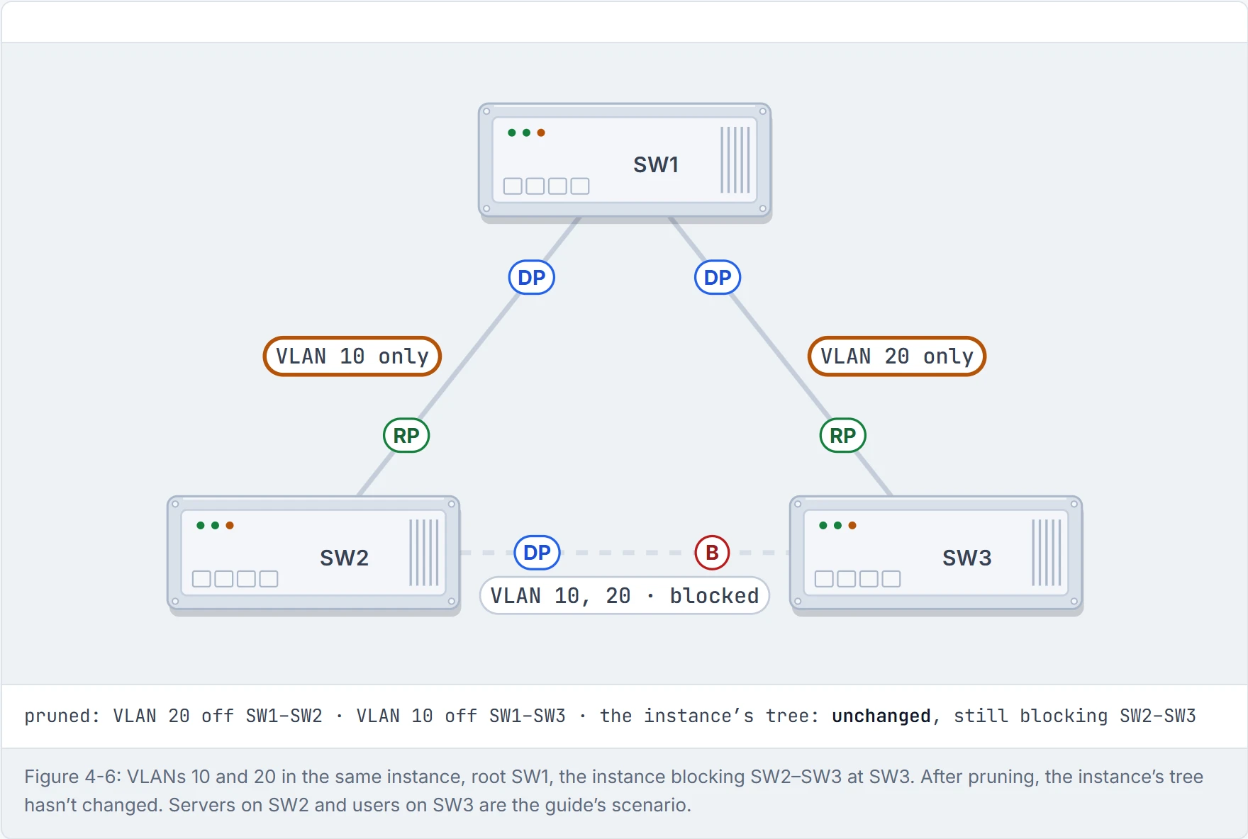
Step 2 of 4 A junior engineer prunes VLAN 20 from SW1–SW2 and VLAN 10 from SW1–SW3, to split the load. The instance doesn’t know: same root, same block.
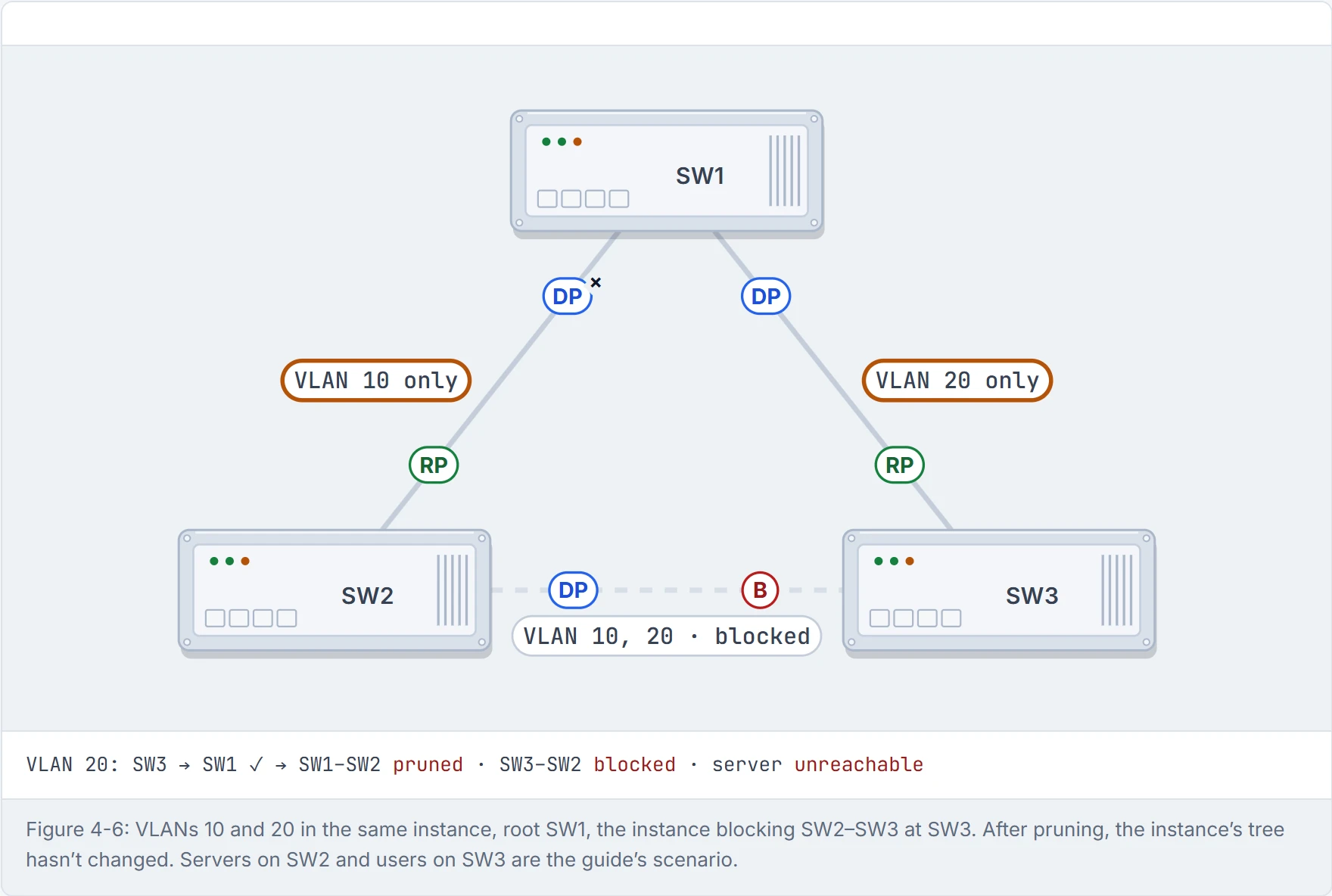
Step 3 of 4 A VLAN 20 frame from SW3 reaches SW1, then finds VLAN 20 pruned towards SW2. The direct SW3–SW2 link is blocked by the instance. Dead end.
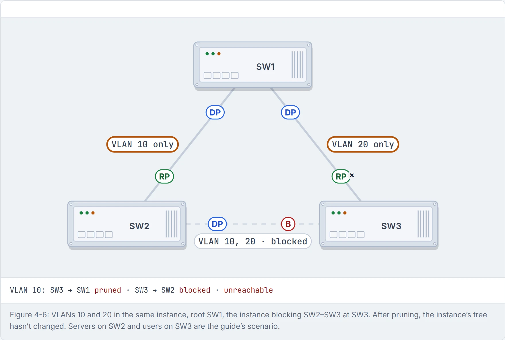
Step 4 of 4 VLAN 10 from SW3 fares no better: pruned towards SW1, blocked towards SW2. The trunks changed; the tree didn’t.
The junior engineer balanced the load beautifully. Across zero working paths.
A region boundary port is one that connects to a switch in a different region, or that hears 802.1D or 802.1w BPDUs. Instances never cross it. What crosses is the CST, derived from the IST; towards PVST+ neighbours, which MST switches detect at the boundary, that happens through PVST simulation. The IST inside each region plus the CST between regions and non-MST switches make one tree, the CIST, the common and internal spanning tree; its root, the CIST root, is the switch that wins overall, and it's the priority the boundary rules below compare against. PVST+ switches don't understand the IST's BPDU, so the boundary sends them one PVST+ BPDU per VLAN, all built from the IST's information: one tree translated into many. Going the other way, the region doesn't map incoming PVST+ BPDUs onto instances: VLAN 1's BPDU is used for the IST, and the simulation only kicks in when a PVST BPDU arrives on the port. It works behind the scenes just like an interpreter at a border who hears one speech and repeats it in every language in the room.
Two designs work:
- The region is root for every VLAN. Make the IST's root better than anything on the PVST+ side. Every boundary port floods the same IST information into every VLAN, and the PVST+ switch does the blocking. In Figure 4-7, SW3 blocks one uplink, and it could balance VLANs by setting costs per VLAN on each uplink.
- The region is root for no VLAN. Then the boundary ports can only block or forward for all VLANs together, so there's no load balancing across them.
The mix, root for some VLANs and not others, is what breaks. Cisco's rules: if the root is inside the region, the PVST+ side's VLANs 2 and up must have worse priorities than the CIST root; if the root is outside, those VLANs must be better than VLAN 1 there. That comparison is the PVST simulation check (a key term in the guide). Break that and the boundary port is blocked as PVST-simulation inconsistent, which may isolate the switches downstream of it: BKN and *PVST_Inc in the output, and %SPANTREE-2-PVSTSIM_FAIL in the log, until the priorities are fixed. Just like when you hire one interpreter for a meeting: it works if one side runs the meeting. If both sides try to chair it, the interpreter stops talking. (The guide calls this blocking "BPDU guard" and "root inconsistent"; Cisco's names are the ones you'll see.)
Continue the lesson
The whole lesson, with its drawings and its questions. The rest of this section and 9 more after it.