
Campus design: access, distribution, core; 2-tier and 3-tier
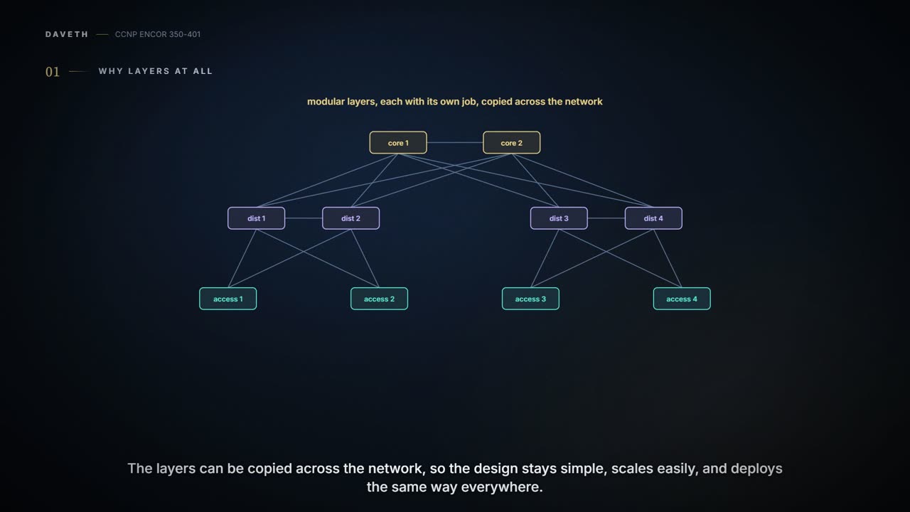
A hierarchical design splits the campus into modular layers that can be copied, which keeps it simple, scalable and fault-contained. The access layer is where users and endpoints connect; the distribution layer aggregates access switches and is the boundary between access and core; the core joins distribution blocks in large networks. Small sites collapse core and distribution into two tiers.
By Arif, founder of Daveth · Updated
The full 9 min walkthrough is in Daveth Pro (Network). See what the plan opens
What this page answers
What are the access, distribution and core layers?
Access gives endpoints and users direct access to the network; distribution aggregates the access layer and is the services and control boundary between access and core; core, also called the backbone, connects distribution layers in large environments. Read it in “4.1 Why layers at all”
Why use a hierarchical campus design?
Layers can be copied across the network, which keeps the design simple and scalable, and they contain faults: a change affects only its part of the network, which helps resiliency and troubleshooting. Read it in “4.1 Why layers at all”
4.1 Why layers at all
A hierarchical LAN design splits the network into modular layers, each with its own job. The layers can be copied across the network, which keeps the design simple, gives an easy way to scale, and a consistent way to deploy. It avoids the alternative, a flat, fully meshed network where every node connects to every other, in which a change touches a large number of systems. The hierarchy contains faults: a change affects only its part of the network, which improves resiliency, and parts can be taken out of service with little effect on the rest, which helps troubleshooting, problem isolation and management. The chapter's opener also credits the design with improving performance, and the quiz answer adds cost-effective redundancy. A town's roads work like a hierarchy too: residential streets feed local roads, local roads feed the ring road, and a burst water main on one street doesn't close the whole town.
The three layers:
- Access: gives endpoints and users direct access to the network.
- Distribution: aggregates the access layer, and is the services and control boundary between access and core.
- Core, also called the backbone: connects distribution layers in large environments.
How many you need depends on the site. A small campus in one building may need only access and distribution; a campus across several buildings will most likely need all three. Either way, each layer provides the same services and the same design methods. You can think of it as flat-pack furniture sold in modules: a studio flat takes two units, a house takes six, and every unit is built the same way.
A flat network is wonderfully simple, right up until someone changes one thing and forty switches notice.
The access layer, also called the network edge, is where end-user devices and endpoints connect: PCs, IP phones, printers, wireless access points, telepresence units and IP cameras, over wired and wireless technologies such as Gigabit Ethernet and 802.11n/ac. Endpoints rarely use their full link for long, but being able to burst to it helps the user's quality of experience (QoE). Access points and IP phones extend the access layer one step further out from the switch. The access layer works like the front door of a shop: the one place every customer comes in, so it's where you check who they are and where they're allowed to go.
The access layer can be segmented into VLANs for performance, management and security. In the hierarchical design the access switches aren't connected to each other: traffic between endpoints on different access switches goes through the distribution layer. And because this is where endpoints connect, it's where the network is protected from them, and where the QoS trust boundary is usually set (05-2). If you've ever worked in an office where every department's door opens onto the same corridor, you've seen the rule: departments don't knock through walls to each other; everyone goes via the corridor.
The access layer is the only layer that has to deal with users directly. It has earned its security features.
The distribution layer aggregates the access switches of a building or campus, and is the boundary between the access layer's Layer 2 domain and the core's Layer 3 domain. That boundary does two jobs. On the Layer 2 side, it limits spanning tree, so Layer 2 faults don't spread. On the Layer 3 side, it's where routing information can be summarised on its way into the core, which shrinks routing tables and cuts protocol overhead for faster recovery (summarisation is 02-6's). The distribution layer acts kind of like the customs desk at a border: it stops trouble from one side wandering into the other, and it hands the other side a tidy summary instead of every passenger's life story.
Distribution switches are deployed in pairs, for redundancy, and the two are connected by a Layer 2 or a Layer 3 link. (The guide's quiz asks for the "maximum" number of distribution switches in a block; its answer, two, is the pair.) In a large campus, a distribution layer in each building also cuts the fibre between buildings, which is expensive: the guide's Figure 22-5, which draws one distribution switch per building, shows three access switches in each of two buildings meshed directly, nine runs, against two between the buildings' distribution switches. If you've ever run deliveries between two warehouses, you know the arithmetic: three rooms each sending a lorry to each of three rooms is nine lorries; one loading dock per building is two lorries, dock to dock.
Nine fibre runs between two buildings is how you find out exactly how much fibre costs per metre.
Once there are more than a few distribution blocks in one location, a core layer is worth considering: it's the backbone and aggregation point for the blocks, and brings scalability, high availability and fast convergence. It can also connect the campus to the other network blocks (data centre, private and public cloud, WAN, Internet edge, network services) and link multiple campuses worldwide. Picture yourself planning an airline: without one, every city needs a flight to every other city; with one, every city needs one flight, to the hub.
Predict before D1: eight distribution blocks, each connected directly to every other. How many links?
D1
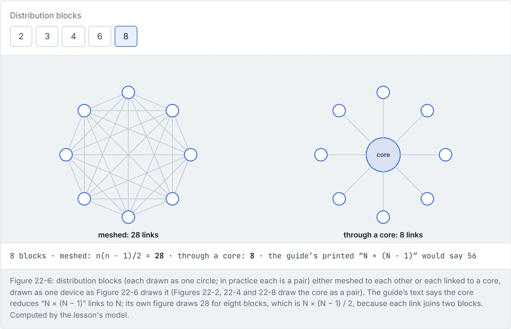
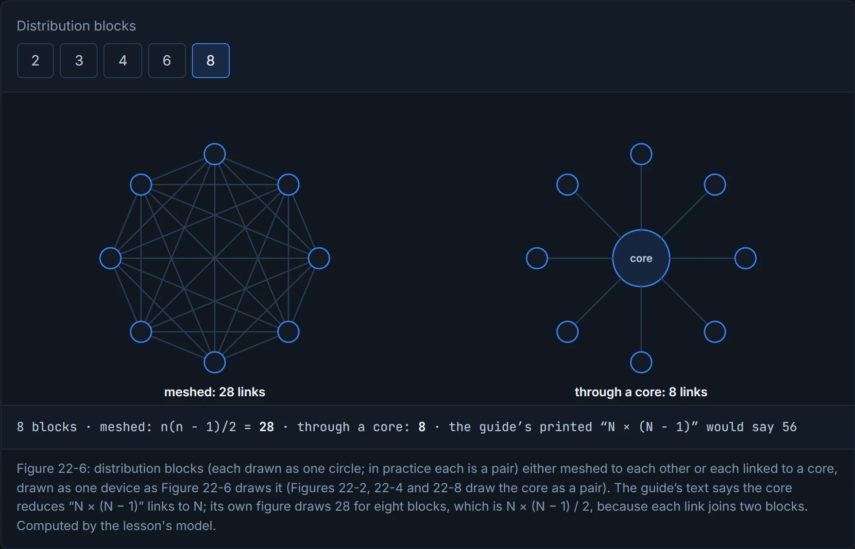
Twenty-eight, against eight through a core. The guide says the core reduces the complexity "from N × (N − 1) to N links for N distributions", but N × (N − 1) counts every link twice: a full mesh of N switches needs N(N − 1)/2 links, and the guide's own Figure 22-6 draws 28 for eight, not 56. The point stands either way: the mesh grows with the square of the blocks, the core with the blocks. Just like when you count the handshakes at a party where everyone greets everyone: ten guests means 45 handshakes, and one host greeting each guest means ten.
A full mesh is the networking equivalent of a group chat where everyone also messages everyone privately.
The guide lists the design options for a campus: two-tier (collapsed core), three-tier, Layer 2 access (STP-based), Layer 3 routed access, simplified campus (06-2), and SD-Access (06-4). A campus is modular, so a real network can mix them, and each option should be judged against the business requirements. Choosing between them works like a house hunt: the number of floors is one decision, what's on each floor another, and a big estate has a bit of everything.
Two-tier, or collapsed core. In a smaller campus, say several departments over several floors of one building, the core may not be needed: the core's job is folded into the distribution layer. That's cheaper (no core devices) without giving up most of the three-tier model's benefits, but future scale, growth and manageability have to be weighed first. In Figure 22-7, one core/distribution pair aggregates the access layer and connects the other network blocks:
- WAN edge: remote data centres, branches and other campuses, and dedicated interconnections to cloud providers such as AWS, Azure and Google Cloud.
- Data centre / server room: the business-critical servers.
- Internet edge: Internet access, e-commerce, remote-branch and remote-VPN connectivity, and cloud access that doesn't need a dedicated interconnection (how the cloud plugs into these blocks: 06-3).
- Network services: WLCs, ISE, TelePresence Manager, CUCM.
Three-tier. A separate core is recommended once more than two pairs of distribution switches are needed: a campus of several buildings each with its own distribution pair; WAN, Internet edge, data centre and services blocks dense enough to affect performance; or access switches spread so widely that running them all back to one collapsed core would need too much fibre. (The guide gives two thresholds. On p604 a core is recommended at more than two pairs of distribution switches, so three or more; p601 says to consider one "beyond three distribution layers", so four or more. Three pairs is the safer reading for the exam, because p604's is the recommendation; and p604's reasons (dense blocks, fibre back to one pair) go beyond the link count.) In Figure 22-8 every building block, or place in the network (PIN), is a hierarchical block with its own distribution pair on the core, except the data centre, which uses a leaf-spine design: the modern alternative for data centres whose traffic is mostly east-west, server to server. The hierarchical design suits north-south traffic, endpoints to the WAN, data centre, Internet or services. Picture yourself running a shopping centre: while it's one corridor of shops, the corridor is the main street; add four wings and you need a central atrium they all open onto.
"We'll add a core when we need one" is how a two-tier campus becomes a three-tier campus on a Tuesday night.
Layer 2 access (STP-based) is the traditional design: Layer 2 access switches, and the distribution layer as the Layer 3 gateway for the hosts. Where possible, keep each VLAN on one access switch: loops are a common point of failure in a LAN even with spanning tree enabled, and one VLAN per switch removes them, at the cost of flexibility, because every host in a VLAN must be on that switch. Some applications need a VLAN on several access switches; that makes a loop, spanning tree blocks links, which wastes bandwidth and can slow convergence. A Layer 2 loop behaves like a roundabout with no exits: a frame that gets on keeps going round forever, so spanning tree closes one of the entrances.
The gateway needs redundancy, so the distribution pair runs a first-hop redundancy protocol (FHRP), giving hosts one MAC and gateway IP per VLAN. HSRP and VRRP are the common ones, and their downside is that hosts send only to the active router, over one uplink, leaving the other uplink unused. Balancing VLANs across the uplinks means configuring it by hand, one distribution switch active for odd VLANs and the other for even, which helps only an access switch that carries both odd and even VLANs: with one VLAN per access switch, each switch still sends everything up one uplink. GLBP load-balances hosts across both uplinks, but works only on loop-free topologies. And all of them need their default settings tuned for sub-second convergence, which costs CPU. (FHRPs themselves are 03-3's and 03-4's. The chapter describes the gateway in IPv4 terms; for IPv6, HSRP version 2 and VRRPv3 both provide a link-local virtual gateway (03-3 section 4.6, 03-4 section 4.3), and GLBP's IPv6 support isn't in the course's sources.)
Continue the lesson
The whole lesson, with its drawings and its questions. The rest of this section and 9 more after it.