
High availability: redundancy, FHRP, SSO
High availability starts with spares: switches and links at Layer 2, paths and routers at Layer 3, and dual power supplies and route processors inside a device. A spare helps only if something notices the failure: an FHRP for the hosts' gateway, stateful switchover between two route processors, and switch stacking or clustering that makes two switches one logical switch.
By Arif, founder of Daveth · Updated
The full 10 min walkthrough is in Daveth Pro (Network). See what the plan opens
What this page answers
What is stateful switchover (SSO)?
A feature that lets a router with two route processors synchronise the configuration and control plane state between them, so the standby can take over when the active one fails. Read it in “4.1 Redundancy: no single point of failure”
What is StackWise Virtual?
Pairing two directly connected switches into one virtual switch. The StackWise Virtual link between them carries data and in-band control traffic, so access switches see one logical switch instead of two. Read it in “4.1 Redundancy: no single point of failure”
What are StackWise and VSS?
Ways to make several physical switches act as one logical switch: stacking, such as StackWise, and clustering, such as the virtual switching system, VSS. They remove spanning tree and FHRP trade-offs in the campus. Read it in “4.1 Redundancy: no single point of failure”
4.1 Redundancy: no single point of failure
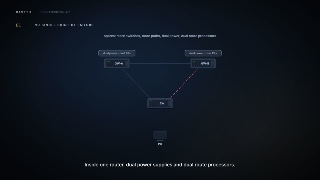
High availability starts with spares. Resiliency at Layer 2 comes from adding switches to the topology, and at Layer 3 from adding paths or routers. Inside one device, routers built for high availability carry redundant hardware such as dual power supplies and dual route processors (RPs). And in the campus design, the distribution switches come in pairs for the same reason (06-1). You can think of it as the spare tyre in the boot: nobody plans to use it, and everyone who's had a puncture on a motorway is glad it's there.
The catch is that a spare is only useful if something notices the failure and starts using it. The guide's Figure 15-4 shows the problem: two routers or two multilayer switches could each be the PC's gateway, joined to its switch by two Layer 2 links, and spanning tree blocks one of those links. The hardware is there. What a failure costs depends on the technique that takes over, which is what the rest of this lesson is about. Two keys to the same front door work like a spare only if someone keeps the second one where you can reach it.
A network with no redundancy has a single point of failure. A network with bad redundancy has two, and a meeting about it.
The PC could point its gateway at 172.16.1.2, but what happens when that device fails? Some operating systems accept several gateways, others don't. First-hop redundancy protocols solve it with a virtual IP gateway shared between the Layer 3 devices: HSRP, VRRP and GLBP. The host keeps one gateway address, and the routers behind it answer for it between them. That acts kind of like a company's main phone number: you call the same number whether Priya or Tom is on reception today.
In the campus design an FHRP runs on the distribution pair, and it isn't free. HSRP and VRRP send each VLAN's traffic to the active router only, leaving one uplink idle unless VLANs are balanced by hand (which helps only an access switch that carries both odd and even VLANs: 06-1); GLBP balances but only on loop-free topologies; and fast failover means tuning the defaults, which costs CPU. How each protocol elects, times out and hands over is 03-3's and 03-4's. For design, the question is only this: the hosts never notice the gateway changed, and you pay for it with an uplink that carries nothing from the hosts, and some tuned timers. If you've ever paid for a second receptionist who spends most of the day waiting for the first one to go on a break, you know the trade.
An FHRP is two routers agreeing to answer to the same name, and taking turns at actually doing the work.
A route processor learns the topology and builds the routing table (RIB). When it fails, routing adjacencies can reset, which means packet loss and instability; it's often better to hide the failure and keep forwarding with the CEF entries already programmed than to drop packets while a second RP rebuilds everything. Hiding it is possible because of how the box forwards. In a centralized architecture the RP's forwarding engine makes every decision; in a distributed one, the line cards carry their own forwarding engines and switch packets without the RP. That's also why distributed platforms scale: the forwarding decision is made closer to the packet's egress, and distributed CEF (dCEF) downloads the CEF tables to every line card so switching is offloaded from the RP. A line card that still holds its forwarding table doesn't need a live RP to keep moving packets, like the wheels of a car that keep turning for a while after the driver takes their foot off the pedal.
Stateful switchover (SSO) lets a router with two RPs synchronise the configuration and control plane state between them. Mirroring that information is called checkpointing; SSO always checkpoints line card operation and Layer 2 protocol state. When the active RP fails, the standby takes control immediately and prevents problems such as interface link flaps. Cisco's 17.9 guide says the same from the standby's side: in SSO mode it starts "fully initialized", synchronises the running configuration and keeps protocol state in step for the features that support SSO. Both RPs must run the same IOS XE image. Picture yourself in a cockpit with a co-pilot who has watched every switch you flipped: if you pass out, they take the controls without anyone restarting the engines.
But here's the part people miss. With SSO alone, Layer 3 forwarding is still disrupted: the switchover makes the routing adjacencies flap, which clears the routing table; the CEF entries are purged; and traffic isn't routed until the topology is relearnt and the forwarding table reprogrammed. The links stay up and the packets stop anyway. The co-pilot kept the plane in the air, and then threw away the flight plan.
SSO alone is a flawless handover in which nobody remembers where they were going.
The guide's fix is one sentence: enabling nonstop forwarding (NSF) or nonstop routing (NSR) tells the router to keep its CEF entries for a short time and keep forwarding through the RP failure until the control plane recovers. They get there differently, and the difference is who has to help.
NSF keeps the forwarding going while the routing protocols recover with their neighbours' help. Cisco Express Forwarding uses the FIB that was current at the switchover to keep forwarding, and the standby starts with FIB and adjacency databases that are mirror images of the active's. The neighbours need to know not to panic. Cisco calls a device NSF-capable if it is configured to support NSF and rebuilds its routing information from its neighbours, and NSF-aware if it runs NSF-compatible software; awareness is on by default for OSPF and EIGRP and off for BGP. Just like when you tell the neighbours you're having the builders in, so they keep treating the house as occupied: the aware neighbour keeps announcing the adjacency (OSPF) or keeps the routes, marked stale (BGP).
Each protocol signals it its own way. An OSPF router restarting gracefully sends Grace-LSAs announcing a grace period, and during it its neighbours, in helper mode, keep announcing it as fully adjacent; OSPFv3 does the same with its own grace-LSA format. A BGP speaker advertises the Graceful Restart Capability in its OPEN message; when the session drops, the peer marks the routes stale and keeps forwarding on them; once the session is back, it replaces them with the fresh updates and deletes whatever is still stale at the End-of-RIB marker, and if the session isn't back within the restart time it deletes them all. EIGRP sets a restart (RS) bit in its hellos. The catch is that NSF needs cooperation: OSPF needs every neighbour on a segment to be NSF-aware, or NSF is disabled on that segment, and for OSPF a topology change during the restart ends it: a helper stops helping when an LSA it would flood to the restarting router changes, a check RFC 3623 suggests leaving on.
NSR takes the neighbours out of it. The switching device preserves its routing state and adjacencies internally, and in most cases the neighbours don't notice; because no help is needed, NSR works where NSF can't, such as with neighbours that don't implement NSF, or when the topology changes during recovery. The price is memory, and possibly CPU. (C4 is Cisco's OSPF NSR chapter; NSR for BGP or OSPFv3 isn't in the course's sources: check on your platform.) Consider it your spare key cut in advance, where NSF is ringing the neighbour who has a copy.
| NSF (graceful restart) | NSR | |
|---|---|---|
| Who keeps the routing state | the neighbours, in helper mode | the device itself, on the standby RP |
| Neighbours must be | NSF-aware | nothing special |
| Neighbours notice | yes, and help | in most cases, no |
| Topology change during recovery | reverts to a normal restart | carries on |
| Cost | neighbour support | memory, and possibly CPU |
Predict before D1: R1 runs SSO alone, R2 is its OSPF neighbour, and RP A fails. Do the links go down? Does routed traffic stop?
D1
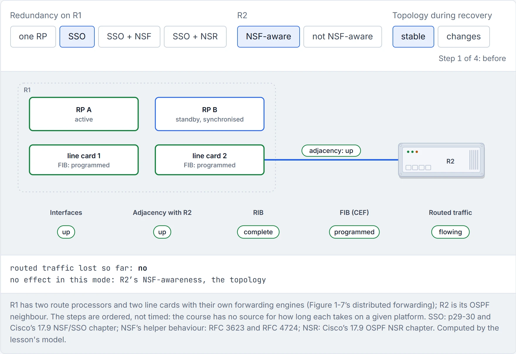
Step 1 of 4 Before: RP A is active; RP B is the standby, synchronised with the configuration and state.
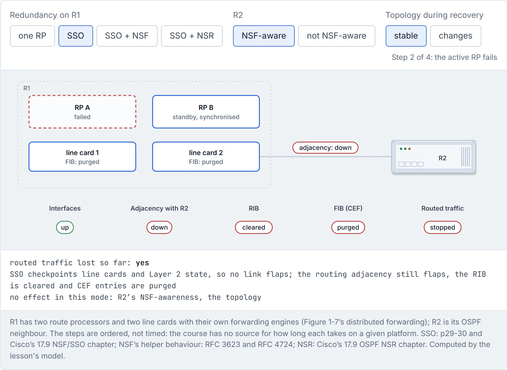
Step 2 of 4 RP A fails. The links stay up, because SSO checkpointed the line cards and Layer 2 state.
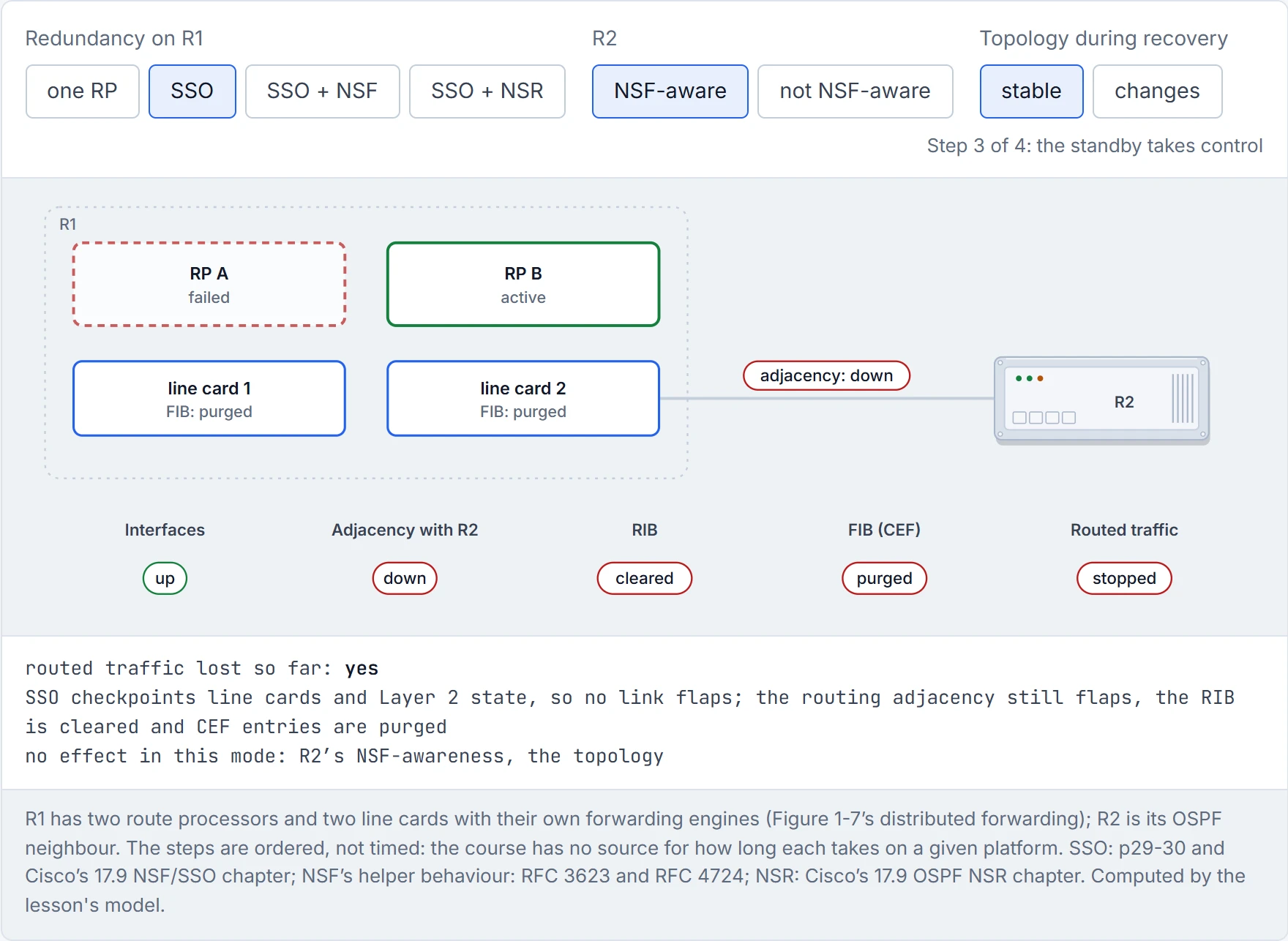
Step 3 of 4 RP B takes control. SSO checkpoints line cards and Layer 2 state, so no link flaps; the routing adjacency still flaps, the RIB is cleared and CEF entries are purged.
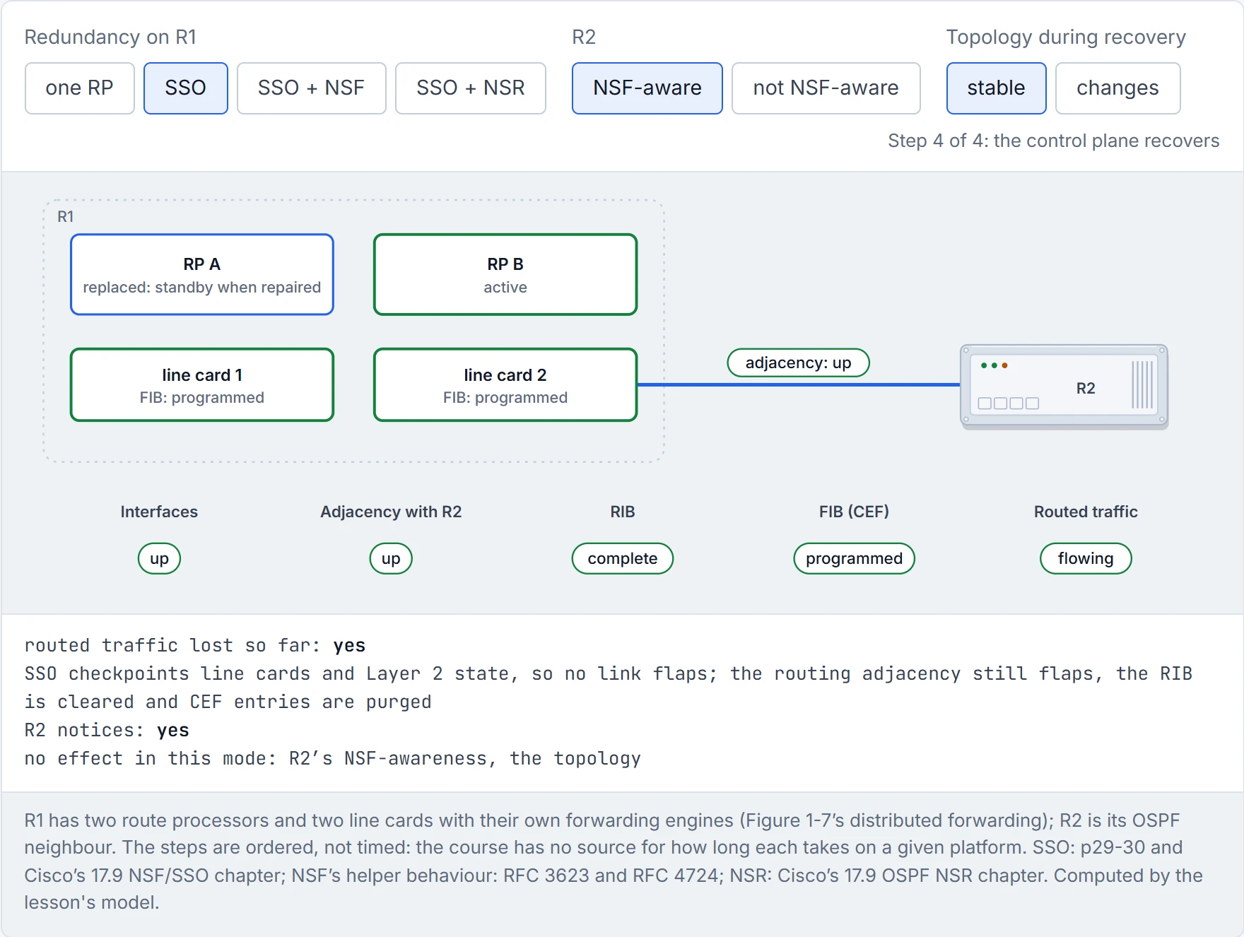
Step 4 of 4 Recovered: the adjacency is back, the RIB relearnt and the FIB reprogrammed. Routed traffic was lost in between.
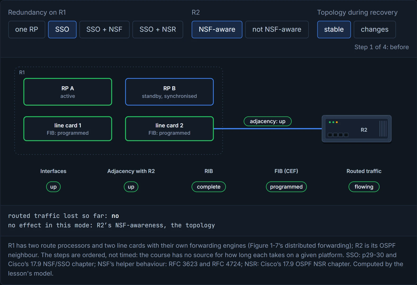
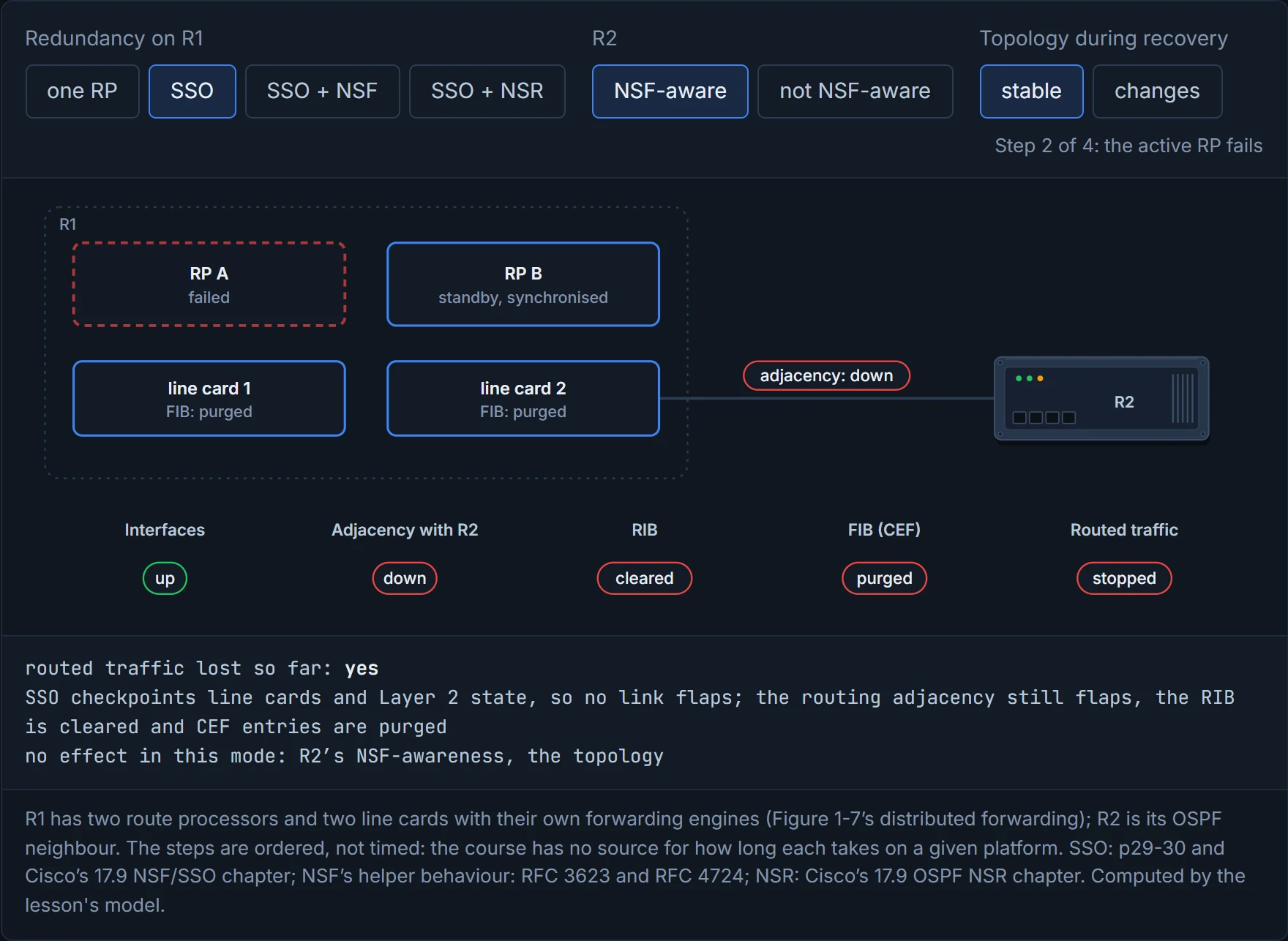
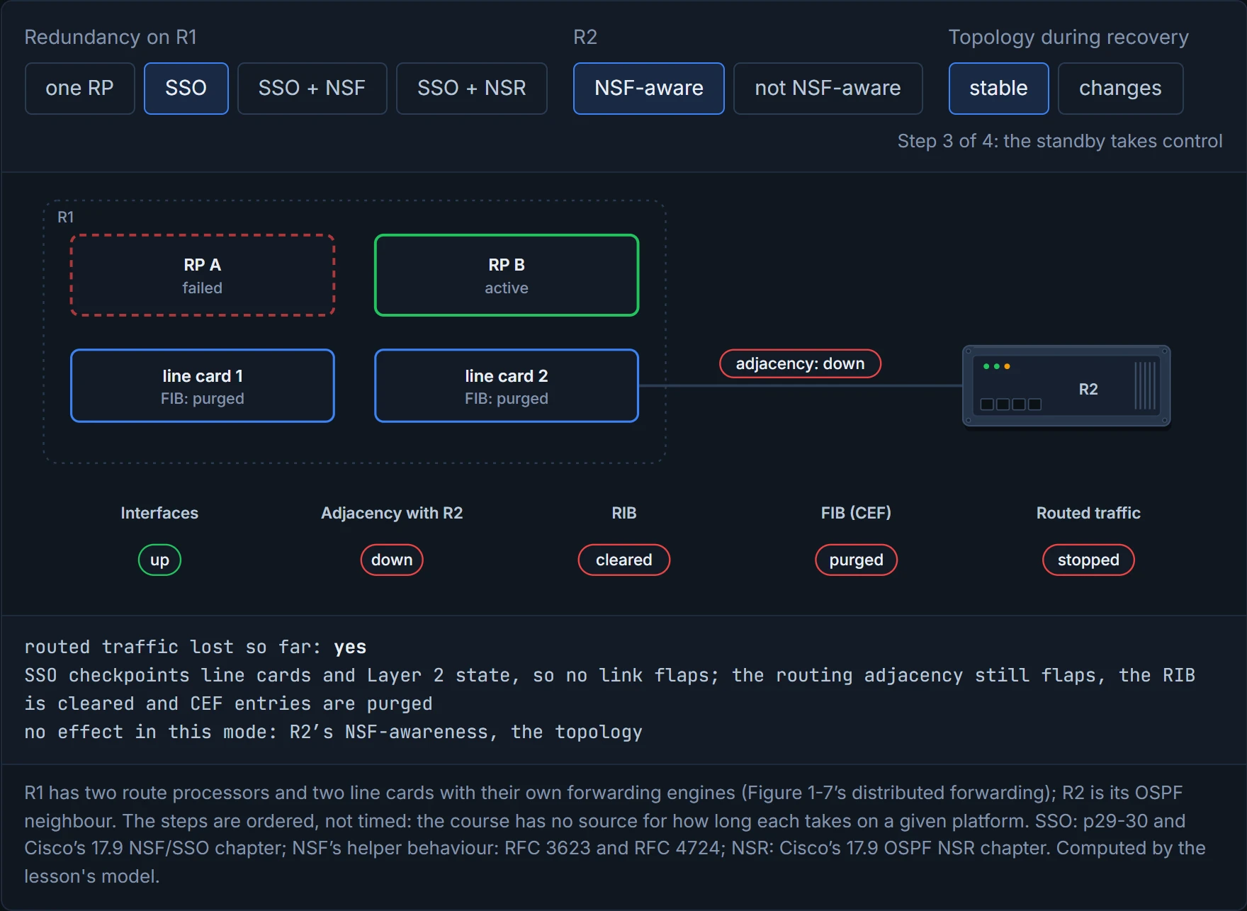
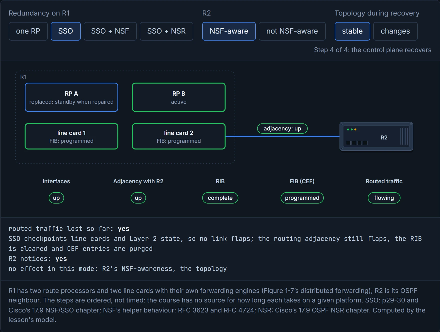
No and yes: SSO kept the links up, and the adjacency flap purged the FIB anyway. Add NSF with an NSF-aware R2 and nothing stops; make R2 unaware, or change the topology mid-restart, and NSF falls back to the SSO-only result. NSR keeps going either way.
NSF is a restart that only works if all the neighbours agree to pretend it isn't happening.
06-1 left a trade: Layer 2 access loses uplinks to STP or an FHRP, routed access can't span VLANs. The simplified campus design gets out of it with switch clustering, such as a virtual switching system (VSS), and stacking, such as StackWise: several physical switches act as one logical switch, in any of the campus blocks. It works like a pantomime horse: two people inside, one horse as far as the audience is concerned.
The guide lists the gains:
- Simplified design: fewer boxes to manage, so less time on provisioning and maintenance.
- No FHRP: the default gateway is on a single logical interface.
- Reduced STP dependence: EtherChannel replaces blocking, but STP stays as a failsafe in case access switches get interconnected.
- More uplink use: with EtherChannel, all uplinks from access to distribution forward.
- Easier troubleshooting: distribution to access is logically hub and spoke.
- Faster convergence: all links forward, and EtherChannel fails over between members in under a second.
- Distributed VLANs: a VLAN can span access switches without blocking any links.
Figure 22-11 shows how: physically, two distribution switches each cabled to both access switches; logically, one distribution switch with a multichassis EtherChannel (MEC), Layer 2 or Layer 3, to each access switch; and with StackWise at the access layer too, one logical switch at each end of one bundle. The guide calls the result loop free, highly available, flexible, resilient and easy to manage, with higher aggregated uplink bandwidth. Figure 22-12 draws VSS at the WAN edge, the Internet edge, network services, the core and each access block's distribution, with StackWise stacks below them; the data centre in the figure is a leaf-spine fabric (ACI), not VSS. Have you ever noticed how a double bed made from two singles pushed together still takes one duvet? The access switch sees one neighbour, bundles both cables, and stops caring how many boxes are upstairs.
Current Catalyst 9000 switches name the two halves differently from the guide. StackWise Virtual pairs two directly connected switches into one virtual switch; the StackWise Virtual link (SVL) between them carries data and in-band control traffic. One switch is elected active and the other standby for the control plane, and both forward data, rather like the senior partner in a two-person firm who does all the talking to clients while both of them do the work; configuration, forwarding and state are synchronised to the standby, and if the active fails the standby takes over by switchover. Both must be the same model on the same software. At the access layer, a Catalyst 9300 stack joins up to eight switches through their StackWise-480 ports; Layer 2 and Layer 3 protocols see one switch, with one active and one standby, and when the active stops responding the standby takes over while the other members carry on without rebooting. A returning active switch doesn't take its role back. That behaves like a relief driver on a long coach trip: once they've taken the wheel, they keep it to the end, and the first driver doesn't grab it back at the next stop.
A stack of eight switches with one brain is either a triumph of engineering or a very well-run committee.
A logical switch removes most failures from the access layer's view, but it adds one. If the last SVL fails, the standby can't tell whether the active is still alive, so to keep the network up it becomes active too. Now there are two active switches with the same IP addresses, SSH keys and STP bridge IDs, which has adverse effects on network stability. It's a bit like two people who both answer to the same name in a busy office: every message arrives, and half of them go to the wrong desk.
Continue the lesson
The whole lesson, with its drawings and its questions. The rest of this section and 9 more after it.