
Time: NTP, and PTP
Passwords, key exchanges, certificate checks and event correlation all need devices' clocks to agree, and clocks drift. NTP keeps them in step through strata: a server attached to the authoritative source is stratum 1, its clients stratum 2, and so on, counting NTP hops, not router hops. Where milliseconds are not enough, PTP, IEEE 1588, takes over.
By Arif, founder of Daveth · Updated

The full 9 min walkthrough is in Daveth Pro (Network). See what the plan opens
What this page answers
What is an NTP stratum?
A level in the chain from the authoritative time source: a server attached directly to it is stratum 1, a client of that server stratum 2, and so on. Stratum counts NTP hops, not router hops, and each level adds its own drift. Read it in “4.1 Why every device needs the same clock”
What is PTP (Precision Time Protocol)?
IEEE 1588's protocol for precision beyond NTP's. Clocks elect a grandmaster, the domain's primary source; a clock with priority1 255 can never be grandmaster. Cisco's implementation is two-step only. Read it in “4.1 Why every device needs the same clock”
4.1 Why every device needs the same clock
A device's system time measures idle periods and computation, and applications use it to tune their own processes. Across a network there are five reasons the clocks have to agree: passwords that change at set intervals; encryption key exchanges; checking a certificate's validity by its expiry date and time; correlating security events across routers, switches, firewalls and access control systems; and troubleshooting, where you line up events from several devices to find the root cause. Think about the last time you tried to work out a row from two people's text messages when one phone was ten minutes fast: every reply seemed to arrive before the question.
A router whose clock went back to its factory date will look at your brand-new certificate and decide it hasn't been issued yet. Certificate validity really is checked against the clock.
Setting every clock right once isn't enough. Clocks tick at slightly different rates, so even perfectly set clocks drift apart. Some devices have only a software clock, which resets when the power does; others have a hardware clock that keeps time through a reset. It's a bit like a classroom of wristwatches set to the same second on Monday: by Friday they disagree, and no watch knows it's the wrong one.
The guide credits RFC 958 with introducing NTP, the Network Time Protocol; today's version is NTPv4, RFC 5905. It runs over UDP: servers listen on port 123, and the guide says the client's source port is dynamic. (RFC 5905 says a client's port is "ordinarily" 123 too, and must be in symmetric mode; which IOS uses is unconfirmed.) Here's the problem it solves. The server's answer takes time to arrive, so by the time you read "it's 09:00:00.000", it isn't any more. NTP measures that delay with four timestamps:
- T1: the client's clock when the request leaves;
- T2: the server's clock when it arrives;
- T3: the server's clock when the reply leaves;
- T4: the client's clock when the reply arrives.
Offset, how far the server's clock is ahead of the client's, is ((T2 − T1) + (T3 − T4)) / 2; the round-trip delay is (T4 − T1) − (T3 − T2). The delay subtracts the time the server held the request, so a slow server doesn't look like a slow network. If you've ever phoned a friend abroad and asked them to read out their kitchen clock, you've done the same sum: you noted when you asked and when you heard the answer, and you assumed the reply took half the round trip.
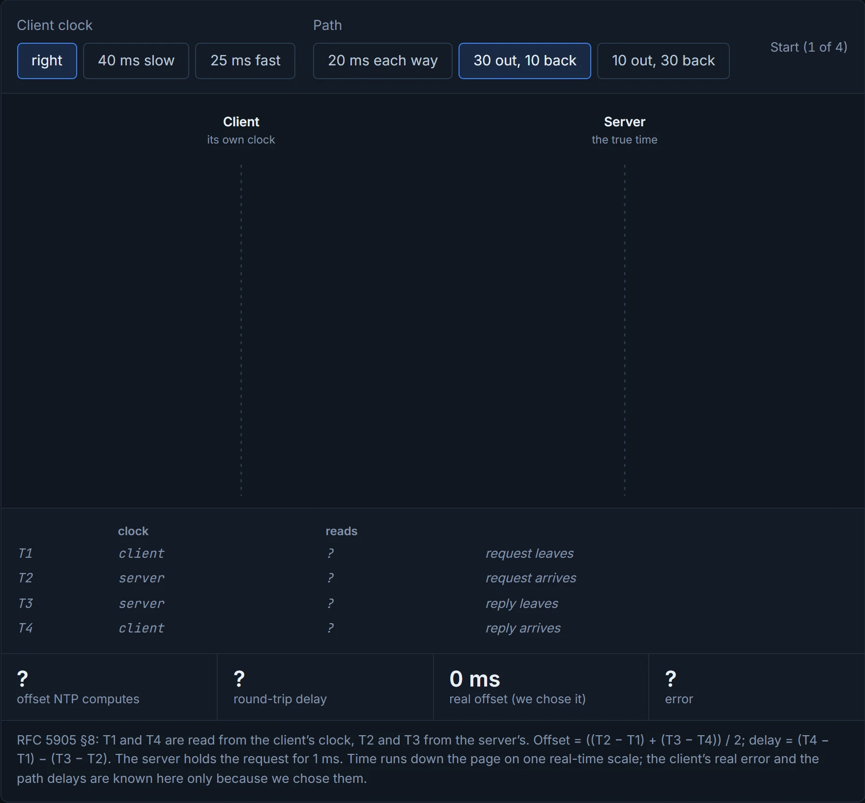
Before you read on, predict: the client's clock is exactly right, the request takes 30 ms and the reply 10 ms. What offset will NTP report? D1 lets you check.
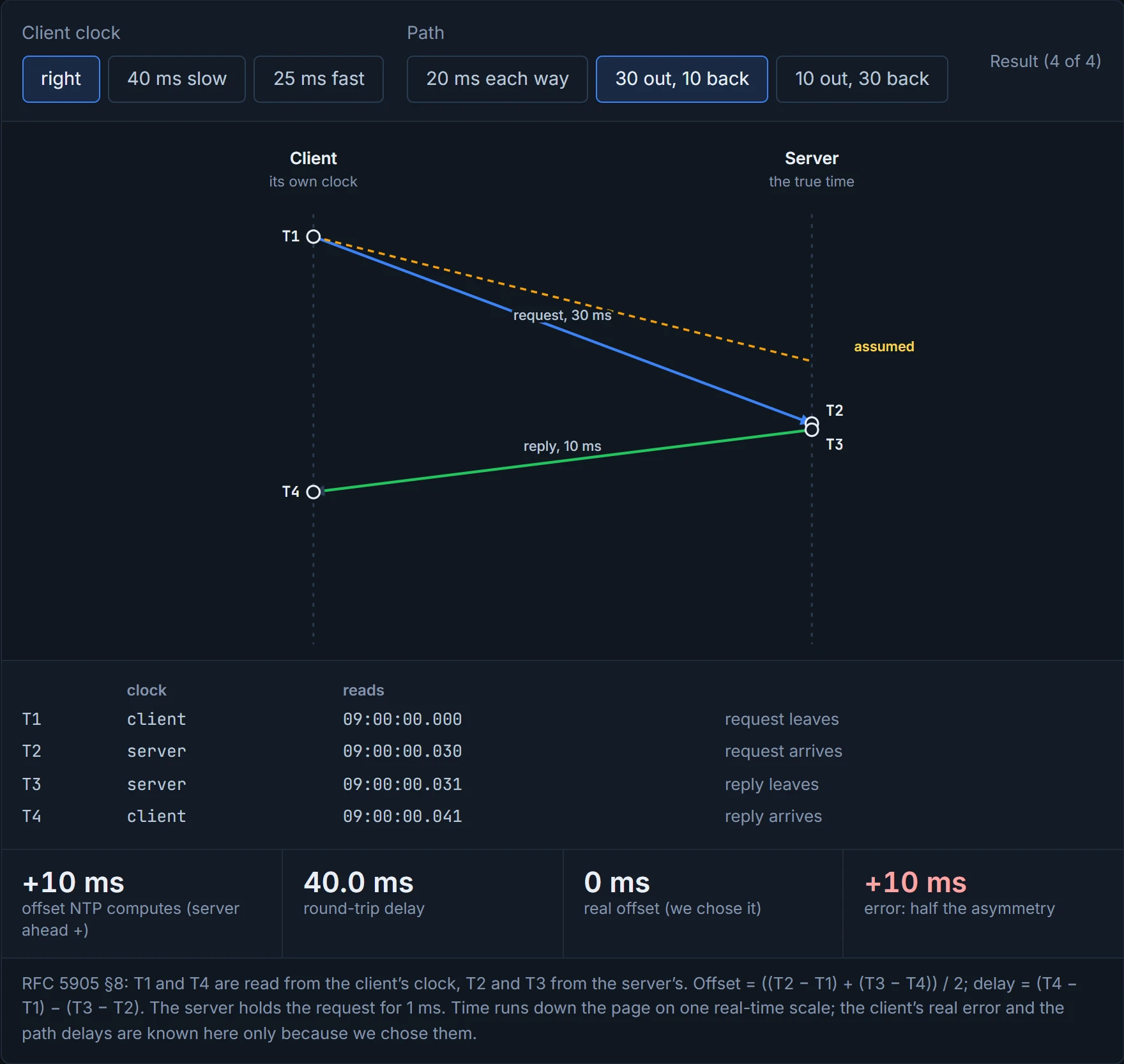
That assumption is the whole catch. The offset is exact only when the trip out takes as long as the trip back. If the request takes 30 ms and the reply 10 ms, the computed offset is wrong by half the difference, 10 ms, and nothing in the four timestamps can reveal it. It can never be wrong by more than half the round trip. The memory hook: time it both ways, trust half, and check who your server trusts.
D1
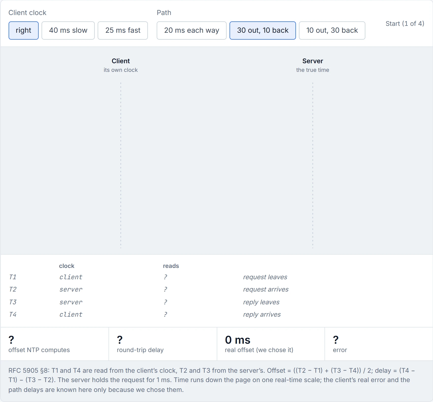
Step 1 of 4 The client’s clock is exactly right, and the path takes 30 ms out and 10 ms back. Only we know either of those. The client is about to ask a server on UDP port 123.
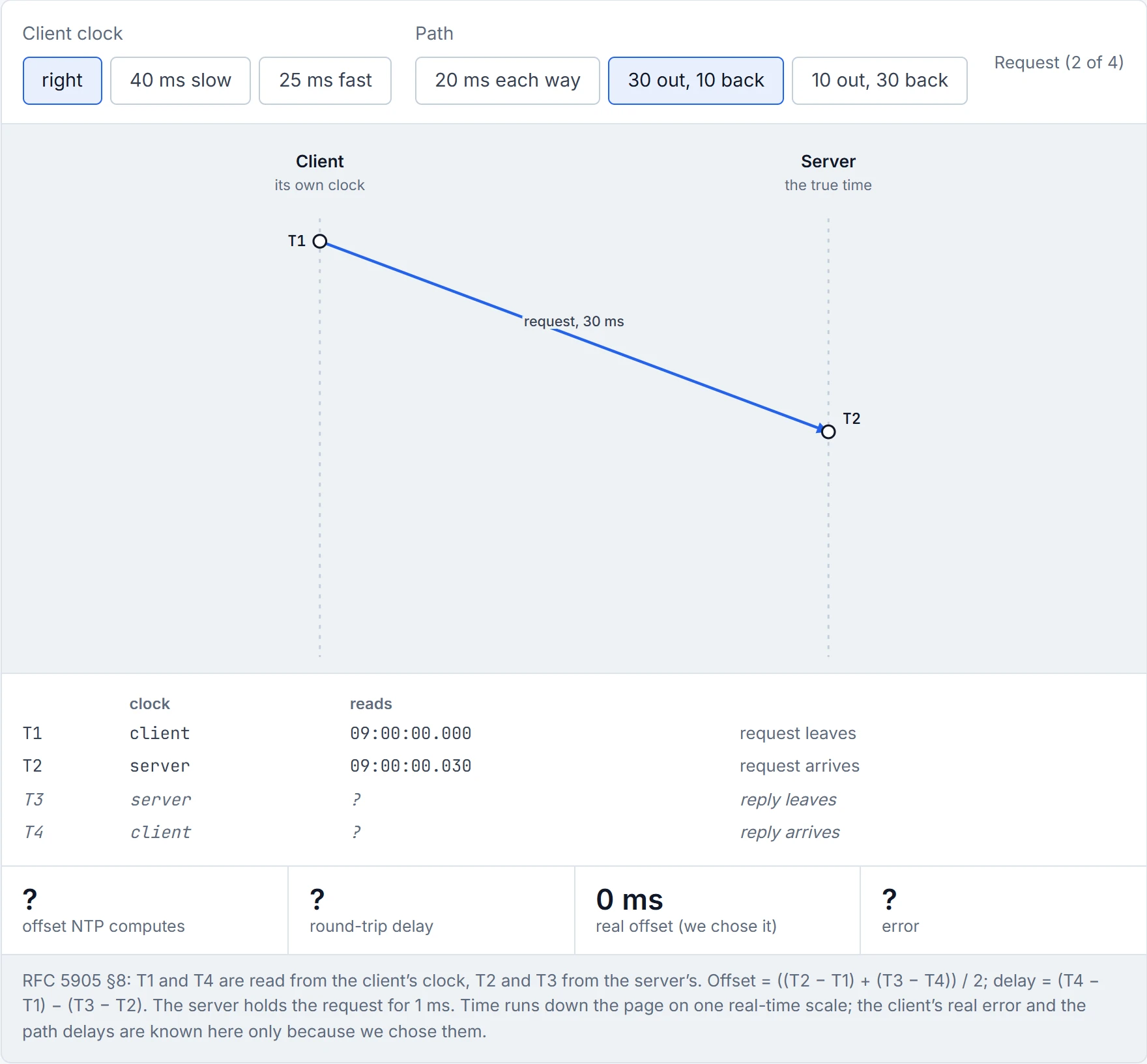
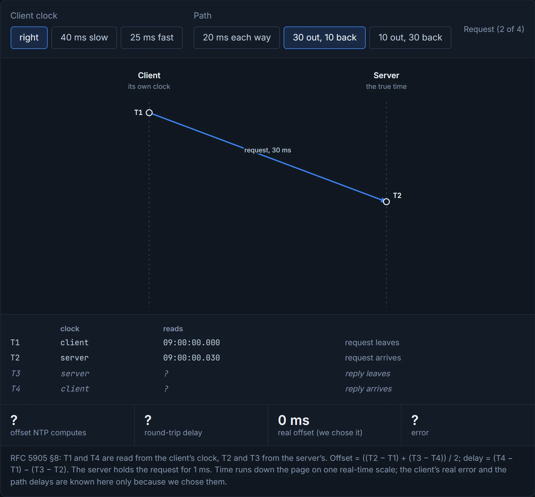
Step 2 of 4 The request leaves at T1 = 09:00:00.000 on the client’s clock and reaches the server 30 ms later, where it’s stamped T2 = 09:00:00.030 on the server’s clock.
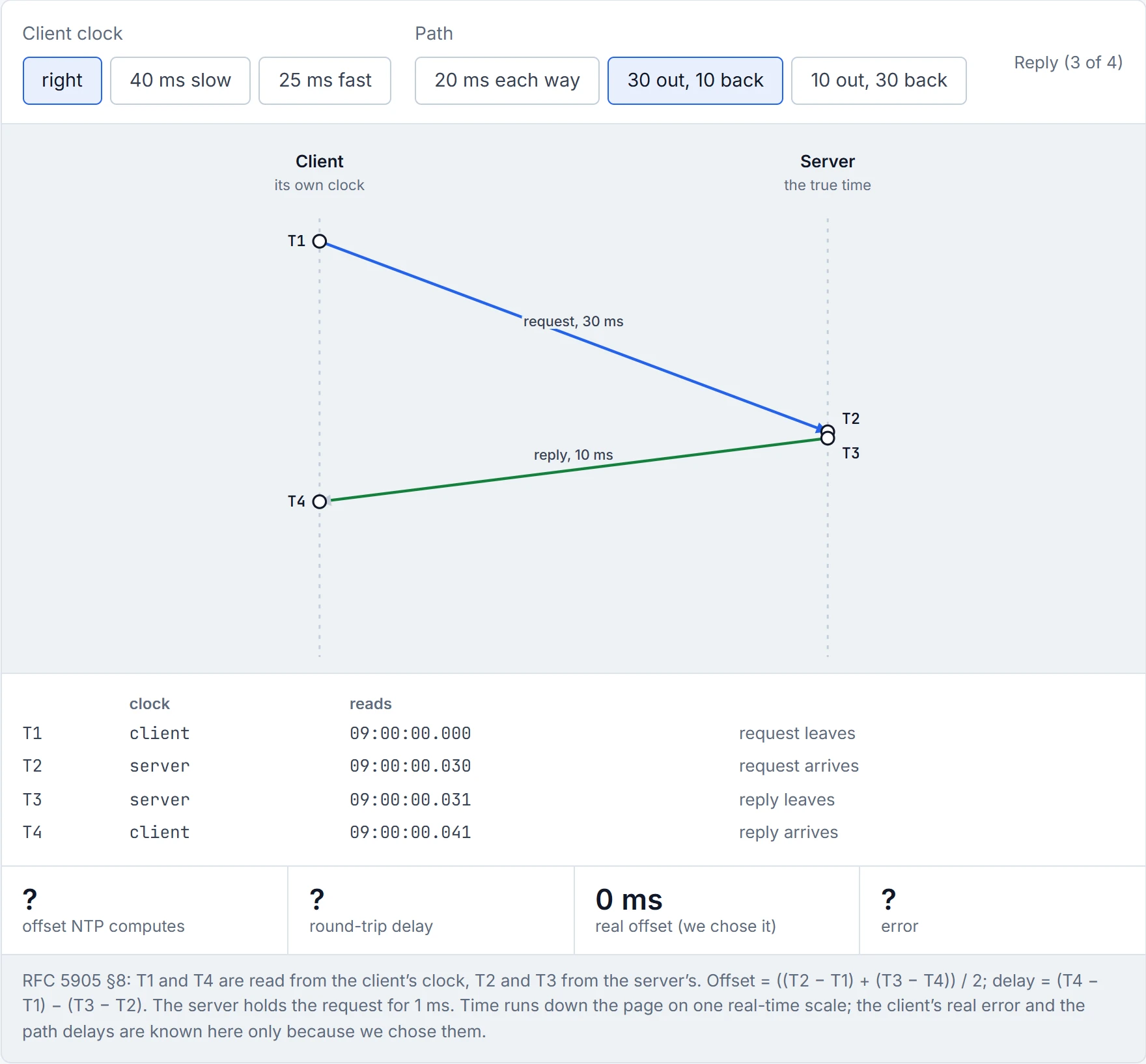
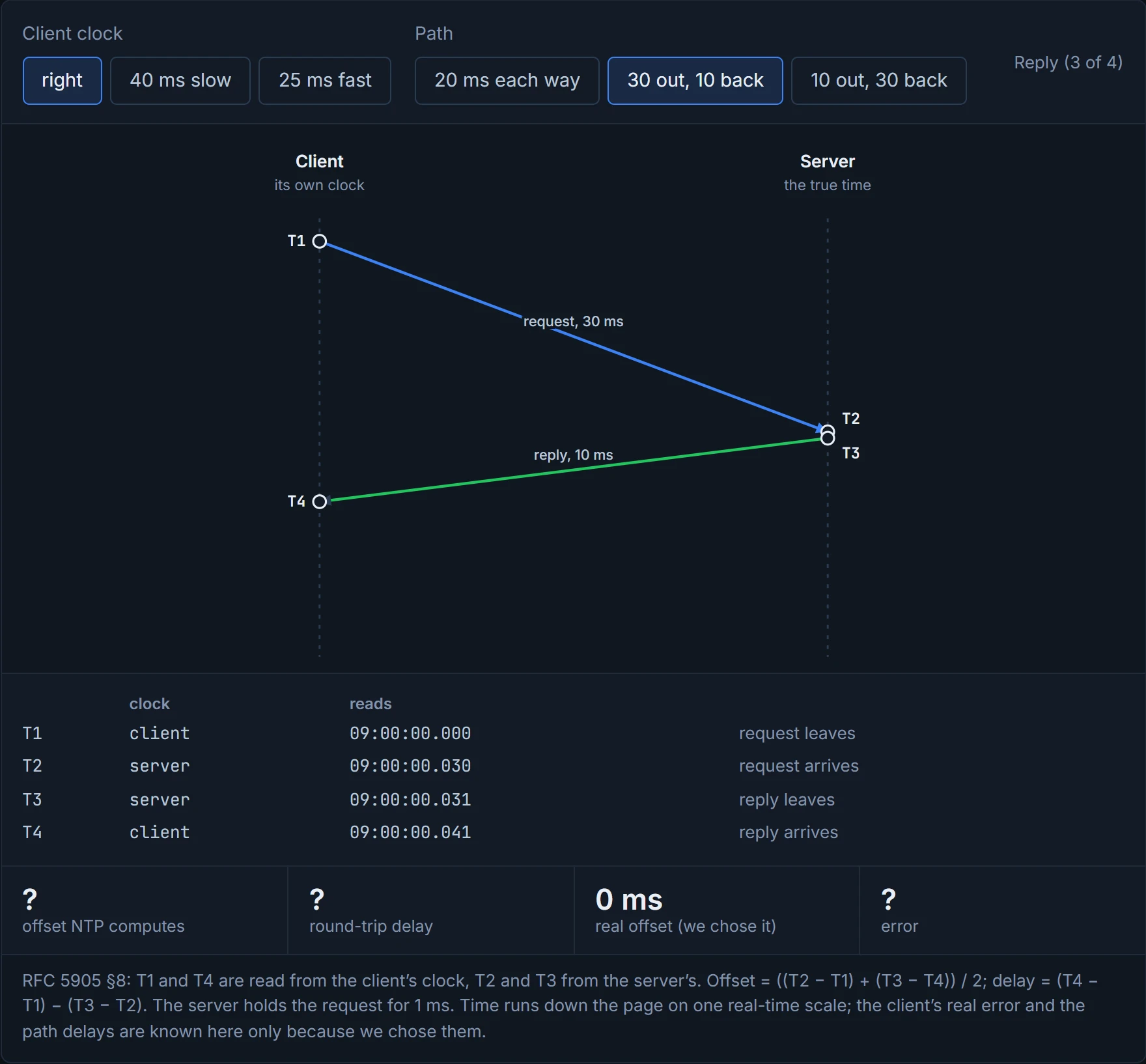
Step 3 of 4 The server replies 1 ms later, T3 = 09:00:00.031. The reply takes 10 ms and lands at T4 = 09:00:00.041 on the client’s clock.
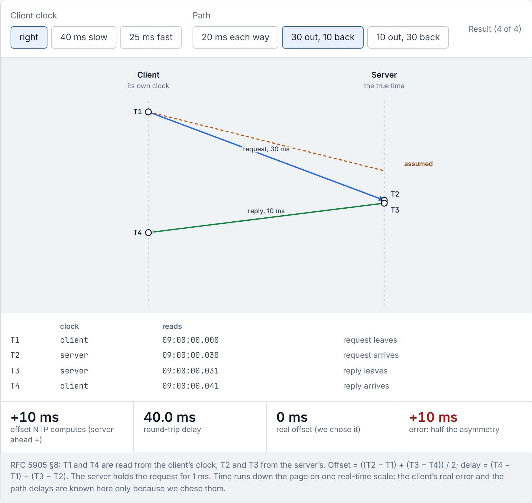
Step 4 of 4 Offset = ((T2 − T1) + (T3 − T4)) / 2 = ((30.0) + (−10.0)) / 2 = 10.0 ms. Delay = (T4 − T1) − (T3 − T2) = 41.0 − 1.0 = 40.0 ms. But the real offset is 0: the client’s clock was right all along. NTP is out by +10 ms, half the 20 ms difference between the two paths, and nothing in the four timestamps shows it. The dashed line is the path NTP assumed.
Getting close takes patience. A client can pull a large error to within a couple of seconds in a few polls, but getting within tens of milliseconds takes hours or days of comparisons, with the client's time drifting toward the server's. What Cisco stresses is how little traffic it needs: "no more than one packet per minute is necessary to synchronize two devices to within a millisecond of one another". That's roughly equivalent to tuning a guitar by ear: the first twist gets you close fast, and the last few cents take a lot of patient listening.
NTP will happily spend a day shaving off a few milliseconds, the most patient thing on your network, and the guide says that really is how long accuracy takes.
NTP is a hierarchy. At the top are authoritative servers with an accurate source (the guide says an atomic clock); clients query them and set their clocks from the answers, and because NTP is an application, a query can cross several routers. Each level is a stratum. A server attached directly to the authoritative source is stratum 1; a client of a stratum 1 server is stratum 2, and so on; the higher the stratum, the more chance of drift from the source, because every level adds its own. Stratum counts NTP hops, not router hops. In Figure 15-1, R1 is stratum 1, R2 (querying R1) is 2, R3 (querying R2) is 3, and R4, which queries R1 across R2 and R3, is stratum 2. Consider it your office's chain of "what time is the meeting?": whoever read the email is first-hand, and anyone who asked them is second-hand, however many desks away they sit.
The guide says the chain "could continue until stratum 15". RFC 5905 fills in both ends: 0 means unspecified or invalid, 1 a primary server (its example has a GPS receiver), 2 to 15 secondary servers synchronised over NTP, and 16 means unsynchronized. So stratum 16 doesn't mean "very far away". It means "don't use me".
The configuration of Figure 15-1 (Example 15-1):
R1(config)# ntp master 1
R2(config)# ntp server 192.168.1.1
R3(config)# ntp server 192.168.2.2 source loopback 0
R4(config)# ntp server 192.168.1.1
ntp server ip-address [prefer] [source interface-id] makes a device a client of that server. source picks the address its queries come from (R3's loopback); you can list several servers for redundancy, and prefer marks the one to take time from; Cisco adds that it "reduces switching back and forth between peers". Whether IOS follows a preferred server over a lower-stratum one isn't said in these sources: unconfirmed. Once a device has synchronised it can serve others, as R2 serves R3. ntp master stratum-number makes a device claim a stratum and serve time from its own clock; the stratum is 1 to 15, and 8 if you leave it out. Now look at R1 again. The guide draws it beside an atomic clock, but Cisco's NTP on the 9300 at 17.9 "does not support stratum 1 service; it is not possible to connect to a radio or atomic clock". So ntp master 1 is R1 claiming stratum 1 from its own clock, and Cisco warns that the command "can override valid time sources, especially if a low stratum number is configured". It's like the most confident person in the room announcing the time without looking at a watch: everyone believes them, because they sounded sure.
ntp master 1 is a router printing its own "world's most accurate clock" certificate: stratum 1 by self-declaration.
IPv6 works the same way: ntp server and ntp peer accept an IPv6 address as well as IPv4, as in ntp server 2001:db8:12::1.
You'll also meet three authentication lines, and they read in order: ntp authenticate turns NTP authentication on; ntp authentication-key 42 md5 aNiceKey defines key 42; ntp trusted-key 42 says which keys a source must use before this device will synchronise to it. Cisco's reference adds a catch: ntp authenticate "does not ensure authentication of peer associations that are created using the ntp server and the ntp peer commands"; the key option on those commands does that.
A client can list several servers but synchronises with only one at a time; it uses another only when that one fails (quiz Q2). Which one? The guide's rule is the lowest stratum, and Cisco says a device "automatically chooses as its time source the device with the lowest stratum number with which it communicates through NTP". Give R4 Figure 15-2's two servers, ntp server 192.168.1.1 and ntp server 192.168.3.3 (R3's address is assumed here), and R4 follows R1 at stratum 1 and is itself stratum 2. If R2 crashes, R4 can't reach R1, so it synchronises with R3 and becomes stratum 4; when R2 recovers, R4 goes back to R1 and stratum 2. It acts kind of like a satnav choosing a route: the best road it can reach, a detour when that road closes, and back again when it reopens.
The guide leaves out two things. First, Cisco adds conditions: NTP avoids an inaccurate device "by never synchronizing to a device that is not synchronized", and "does not synchronize to a device whose time is significantly different than the others, even if its stratum is lower". The lowest stratum wins among sources that agree. (RFC 5905 ranks the survivors by stratum times one second plus each one's estimated error, so stratum dominates without being everything.) Second, look at R3 when R2 dies. R3's only server was R2, so from that moment R3's clock runs on its own, corrected by nobody. It goes on offering stratum 3, because RFC 5905's sample code changes a server's advertised stratum only when it steps its clock or hears from its own server, and R4 takes it, exactly as the guide draws. Not for ever, though. The same code adds 15 ppm to R3's root dispersion every second nothing corrects it, and "When the dispersion exceeds MAXDIST (1 s), the server is considered unfit for synchronization": about 18 hours later (1 s at 15 ppm) R4 would drop R3 and have no usable server at all. How IOS XE times this is unconfirmed. Have you ever noticed how the person giving the most confident directions is sometimes the one whose map is out of date? That's R3.
Before you look at D2, predict: R1 itself crashes. What stratum does R4 end up at, and whose clock is it really following?
D2
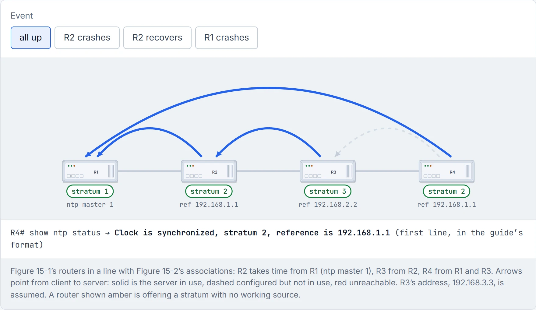
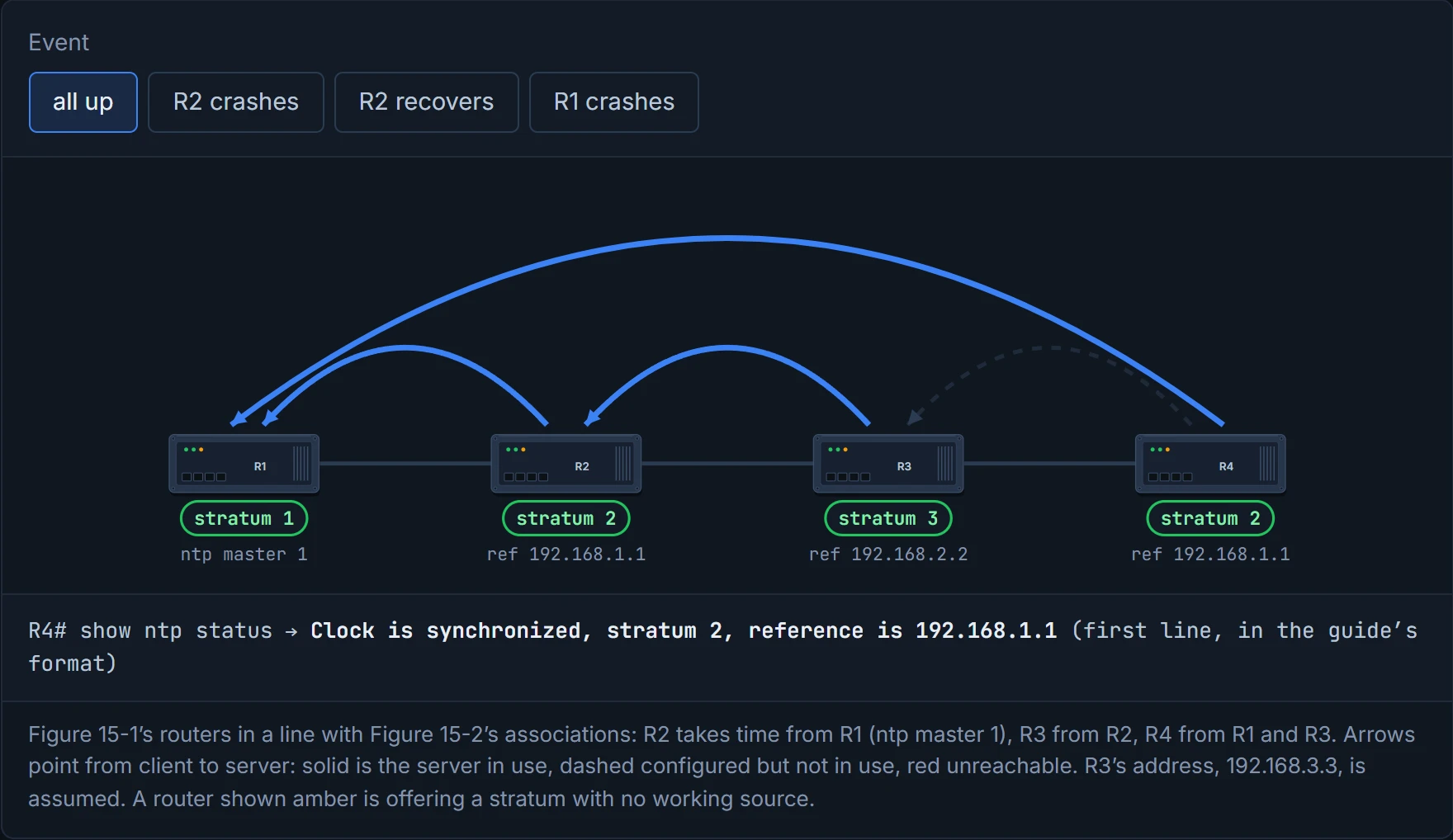
R4 drops from stratum 2 to stratum 4 without a word of complaint: NTP happily settling for news three people removed from the source.
This is what 3.3.a means by "interpret". show ntp status shows, in the guide's list: whether the clock is synchronized, its stratum and its reference (its own clock or a server's address); the clock's frequency and precision; NTP uptime and granularity; the reference time; the clock offset and the delay (the output's field is root delay, "Total delay along the path to the root clock", not just the hop to the server one stratum up); root and peer dispersion; the loop filter state; and the poll interval with the time since the last update. From Example 15-2:
R1# show ntp status
Clock is synchronized, stratum 1, reference is .LOCL.
R2# show ntp status
Clock is synchronized, stratum 2, reference is 192.168.1.1
nominal freq is 250.0000 Hz, actual freq is 249.8750 Hz, precision is 2**10
clock offset is 1192351.4980 msec, root delay is 1.00 msec
root dispersion is 1200293.33 msec, peer dispersion is 7938.47 msec
loopfilter state is 'SPIK' (Spike), drift is 0.000499999 s/s
R3# show ntp status
Clock is synchronized, stratum 3, reference is 192.168.2.2
(Lines trimmed; the full outputs are on p398.) Read it down the chain: the stratum goes up by one at each router, and each reference is the server one level up, with R1's being .LOCL., its own clock. Now look hard at R2. "Clock is synchronized", and its clock offset is 1,192,351 ms: nearly twenty minutes. The loop filter state is 'SPIK'. In RFC 5905's clock discipline, an offset over 125 ms isn't acted on at once: it's treated as a spike, and only if it lasts 900 s is the clock stepped. But 1,192 s is also past the RFC's 1,000 s panic threshold, where the reference implementation "SHOULD" give up and exit. IOS doesn't panic by default; ntp panic update makes it reject updates that large. What R2 does next is unconfirmed. Its root dispersion, 1,200,293 ms, is its own error estimate, as large as its offset, and its system poll interval is 64 s against R1's 16 (Example 15-3's poll column is a different counter, one per association). So the first line tells you R2 has chosen a server. It doesn't tell you R2's time is right. It's basically like a station board saying the 9:15 "is on its way": true, and silent on whether it's twenty minutes late.
Example 15-2's R2 is "synchronized" and twenty minutes out, which is also how most office wall clocks would describe themselves.
Two field definitions need care. The guide calls root dispersion "the calculated error of the actual clock attached to the atomic clock" and peer dispersion "the root dispersion plus the estimated time to reach the root NTP server". RFC 5905 defines root dispersion as the "Total dispersion to the reference clock" and root delay as the "Total round-trip delay to the reference clock"; Cisco describes peer dispersion as "Dispersion of the synchronized peer". Dispersion is NTP's estimate of the maximum error, and it grows at 15 ppm, about 1.3 s a day, while nothing corrects it. For a server reached over IPv6 the reference ID isn't the address itself: RFC 5905 uses the first four octets of an MD5 hash of it; how IOS prints the "reference is" line then is unconfirmed.
show ntp associations is the short version. Example 15-3:
R1# show ntp associations
  address         ref clock       st   when   poll reach  delay  offset   disp
*~127.127.1.1     .LOCL.           0      0     16   377  0.000   0.000  1.204
R2# show ntp associations
*~192.168.1.1     127.127.1.1      1    115   1024     1  1.914   0.613 191.13
R3# show ntp associations
*~192.168.2.2     192.168.1.1      2     24     64     1  1.000   0.500 440.16
 * sys.peer, # selected, + candidate, - outlyer, x falseticker, ~ configured
(The guide's prompts read SW1# and SW2#; the text makes them R2 and R3.) 127.127.1.1 is the device's own clock, as set up with ntp master, listed at stratum 0: RFC 5905 notes that reference clocks "normally appear at stratum 0", and R1 itself is stratum 1 (Example 15-2). The columns: address is the server and ref clock that server's own reference; st is that server's stratum; when, seconds since its last packet; poll, the polling interval in seconds; reach, a bit string in octal, one bit per recent poll with the newest on the right (RFC 5905 §9.2's shift register), so 377 is eight answers in a row and 1 is only the latest. Read it as octal: 17 is binary 1111, the last four polls answered; 37 is 11111, five; 77 is 111111, six; and 376 is 11111110, seven answers and then a miss on the newest; delay and offset, in milliseconds, are D1's two sums; disp is dispersion. * marks the server you're synchronised to and ~ a configured one; +, #, - and x are the selection verdicts. In RFC 5905's terms a falseticker (x) is "a clock that shows misleading or inconsistent time", and an outlier (-) is one the cluster step discards. So R2 and R3 in Example 15-3 have each heard one answer so far. Think of it as the reach column being eight tick boxes for "did they pick up?", written in octal for good measure. Cisco's command reference prints a different legend under its sample ("* master (synced), # master (unsynced), + selected, - candidate"), so read the legend under the output you've got.
In the client/server model, the client changes its time to the server's and the server never changes to the client's; RFC 5905 puts it as clients pulling synchronization, while "Peers both push and pull synchronization to and from each other". Most organisations take time from an external server (the guide names universities, governments and pool.ntp.org), and a common design has two devices each query a different external source, then peer their local stratum 2 devices with each other. Picture yourself and a colleague each checking a different official clock website, then agreeing that if one site goes down, you'll both set your watches by the other.
ntp peer ip-address makes the relationship symmetric: each peer acts as client and server to the other, and they move their times toward each other. It's for designs where devices back each other up and use different primary sources (Figure 15-3, where R1 takes time from 100.64.1.1 and R2 from 100.64.2.2; Example 15-4: R1 ntp peer 192.168.2.2, R2 ntp peer 192.168.1.1, peering on loopbacks). Cisco calls this symmetric active mode and recommends it where "a number of mutually redundant servers are interconnected via diverse network paths". In a way, it's just two people splitting a restaurant bill: neither pays all of it, and both move toward the middle. The guide's NOTE adds that a peer with an authoritative source treats its peer as an equal and shifts toward it, and that peers adjust "at a maximum rate of two minutes per query". No Cisco or RFC source found gives that figure, so hold the number as unconfirmed.
NTP peers are the only relationship in networking where both sides agree to meet halfway, and they really do move their clocks toward each other.
NTP's milliseconds are plenty for logs and certificates. Some systems need far better: Cisco's PTP chapter names smart-grid power automation (peak-hour billing, virtual power generators, outage monitoring) as needing "extremely precise time accuracy and stability". That's the job of the Precision Time Protocol, PTP, defined in IEEE 1588.
The obstacle is the network itself. A busy switch buffers packets, and the wait varies, so the delay one way isn't the delay the other way. PTP, like NTP, averages the two directions, and Cisco is blunt about it: the calculation "assumes a symmetrical communication path; switched networks do not necessarily have symmetrical communication paths, due to the buffering process". That's D1's error again, now made by a queue inside a switch. Imagine if a courier took the motorway to your house and the back roads home: halving the round trip would put your house in the wrong place.
PTP answers with timestamps taken at the port and with switches that take part. Event messages are timestamped as they reach or leave a port: Sync, Delay_Req, Pdelay_Req, Pdelay_Resp. General messages aren't: Announce, Follow_Up, Delay_Resp, Pdelay_Resp_Follow_Up. The exchange is NTP's with the roles turned round. The master sends Sync and notes t1; the slave notes t2 when it arrives; the master sends t1 in a Follow_Up; the slave sends Delay_Req at t3; the master notes t4 when it arrives and sends it back in a Delay_Resp. The slave now holds all four and computes its offset and the mean path delay, assuming the path is the same length both ways. Cisco's implementation is two-step only (t1 travels in that separate Follow_Up), and a one-step message from a grandmaster is dropped. Cisco's chapter ties accuracy to timestamps taken in hardware, noting that accuracy suffers where PTP messages are forwarded without them. From the four times, the offset from master is ((t2 − t1) − (t4 − t3)) / 2 and the mean path delay ((t2 − t1) + (t4 − t3)) / 2, less any correction fields. Mind the sign: PTP's offset is slave minus master, NTP's is server minus client.
Who is the master? The Best Master Clock Algorithm (BMCA) runs on every port, every Announce interval, and compares in order: Priority1 (0-255, default 128), Class, Accuracy, Variance, Priority2 (0-255, default 128), then a 64-bit unique identifier. A clock with priority1 255 can never be grandmaster.
PTP's grandmaster election lets any clock make itself unelectable with a single number: priority1 255.
The clock types:
| Clock | What it does |
|---|---|
| grandmaster | the domain's primary source, usually fed by GPS or an atomic clock |
| ordinary | one PTP port; an end node, master or slave |
| boundary | several ports: the port towards the best clock becomes slave and the rest master; it synchronises upstream and serves downstream |
| transparent, end to end (E2E) | measures how long each Sync and Delay_Req spent inside the switch (the residence time) and adds it to the message's correction field; the link delay itself isn't corrected |
| transparent, peer to peer (P2P) | the same, plus the upstream link delay, measured with Pdelay messages |
Continue the lesson
The whole lesson, with its drawings and its questions. The rest of this section and 9 more after it.