
OSPFv3 and address families
OSPFv3 is not compatible with OSPFv2 on the wire, but the machine underneath is the same, and it supports both IPv6 and IPv4 address families. Neighbours talk over link-local addresses, the router ID is still a 32-bit value, and interfaces are enabled directly instead of with network statements. The LSDB changes most: new LSA types carry the prefixes.
By Arif, founder of Daveth · Updated
The full 14 min walkthrough is in Daveth Pro (Network). See what the plan opens
What this page answers
How do you configure OSPFv3 for IPv4 and IPv6?
ipv6 unicast-routing, router ospfv3 with a process ID and router-id, optionally address-family ipv6 or ipv4 unicast, then on each interface ospfv3 process-id ipv6 area area-id or ipv4. There are no network statements. Read it in “Switching it on: the configuration, in both forms”
How do you troubleshoot OSPFv3 neighbours?
Use the same checks as OSPFv2 with ospfv3 in place of ip ospf: show ospfv3 ipv6 neighbor, then the interfaces and their areas, timers and router IDs. Read it in “Reading it back”
Three transit links with no global addresses
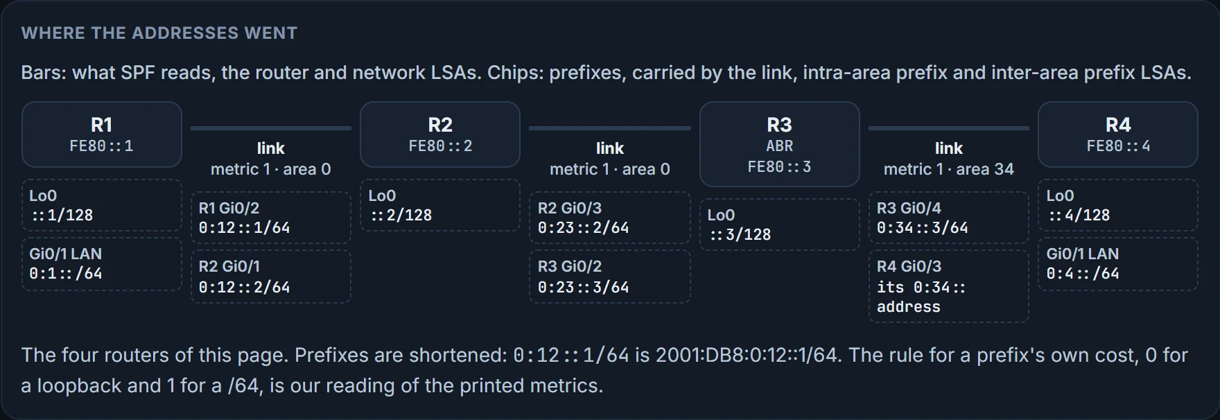
Here's a network you know the shape of already: four routers in a line, R1, R2, R3, R4. Area 0 holds R1, R2 and R3; area 34 holds R3 and R4, so R3 is the ABR. Every link has a global IPv6 /64, and every router a /128 loopback. R1's LAN is 2001:db8:0:1::/64, and R4 has one too, 2001:db8:0:4::/64.
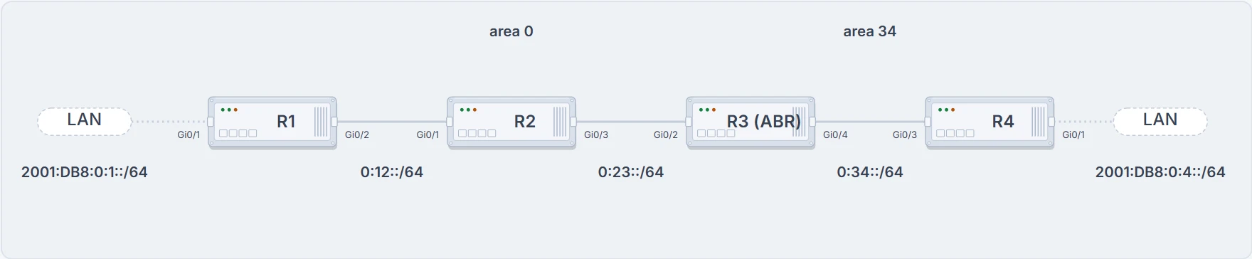
R3 is the ABR between area 0 and area 34. Each router's link-local addresses are set by hand to its own number, FE80::1 on R1 to FE80::4 on R4, and each has a loopback 2001:DB8::N/128. The terminals on this page come from these four routers; outputs from another network say so.
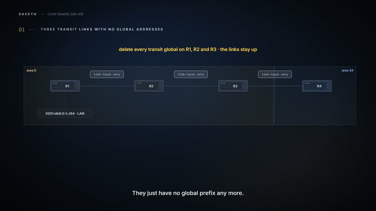
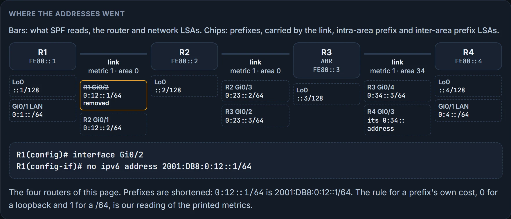
R4 reaches R1's LAN across three transit links: 2001:db8:0:34::/64, 0:23:: and 0:12::. Now delete the global address from every one of those transit interfaces on R1, R2 and R3. The links stay up; R1's, R2's and R3's ends just have no global prefix any more (R4 keeps its own on the R3-R4 link).
Before you read on: does R4 still reach 2001:db8:0:1::1? And what happens to R4's routing table? Your OSPFv2 instinct has a clear answer: in OSPFv2 the interfaces' network addresses are what the routing is built on.
Here's R4 afterwards:
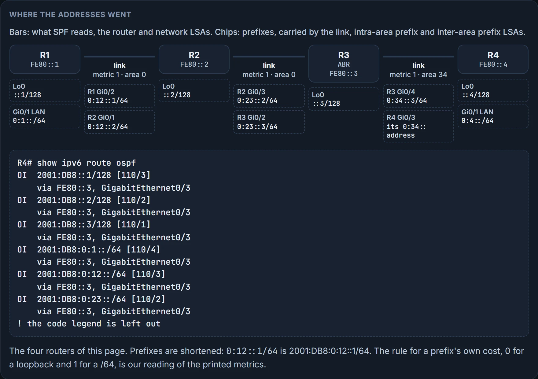
R4# show ipv6 route ospf
OI  2001:DB8::1/128 [110/3]
    via FE80::3, GigabitEthernet0/3
OI  2001:DB8::2/128 [110/2]
    via FE80::3, GigabitEthernet0/3
OI  2001:DB8::3/128 [110/1]
    via FE80::3, GigabitEthernet0/3
OI  2001:DB8:0:1::/64 [110/4]
    via FE80::3, GigabitEthernet0/3
! the code legend is left out here
Before the change, that table also held 2001:db8:0:12::/64 and 0:23::/64. The transit networks have gone from it, and the three loopbacks and R1's LAN are still there. And the ping:
R4# ping 2001:DB8:0:1::1
Type escape sequence to abort.
Sending 5, 100-byte ICMP Echos to 2001:DB8:0:1::1, timeout is 2 seconds:
!!!!!
Success rate is 100 percent (5/5), round-trip min/avg/max = 6/6/6 ms
! still reaches R1's LAN
R4#
R4 still has full connectivity to those networks, because the topology is built on the link-local addresses: as long as the source and the destination have routes to each other, they can talk. It's a demonstration of a mechanism, not a design to copy. Anything that needs a transit interface's own global address, a ping to R2's old 0:12:: address say, now has nothing to aim at.
Hold that result. It's the whole lesson in one ping, and the database section takes it apart. For now, one sentence of why: in OSPFv2, the interface's network addresses build the adjacency and connect the devices; in OSPFv3 the LSDB builds its shortest path tree on links, not networks. So transit links need only link-local addresses to forward traffic, and their global addresses can go while R4 keeps reaching R1's 2001:db8:0:1::/64.
So which of your OSPFv2 habits are still true? That's the audit. Each section below takes one habit, and you call it before the output does: keep it, keep it in a new form, or drop it.
How they talk: keep the conversation, change the addresses
Start with the promise. OSPFv3 isn't backward compatible with OSPFv2, but the mechanisms you've learned for OSPFv2 are essentially the same, and OSPFv3 supports both the IPv4 and the IPv6 address families. Not compatible on the wire, same machine underneath. Remember both halves.
The conversation is the adjacency lesson's. OSPFv3 uses the same five packet types and the same logic as OSPFv2: hello, database description, link-state request, link-state update, link-state acknowledgment. Same protocol number too: OSPFv3 packets use protocol 89. Keep.
What changes is the envelope. OSPFv3 runs directly over IPv6, and its packet header has fewer fields; RFC 5340 is the reference for every difference in depth. And every address in the conversation changes. Routers send from the local interface's IPv6 link-local address, and they send either to a unicast link-local address or to a link-local-scoped multicast address, depending on the packet. Two multicast groups: FF02::5 is AllSPFRouters and FF02::6 is AllDRouters.
Predict before the list: a router that isn't the DR or BDR has an update to flood on a LAN. Which address does it send it to?
- Hellos: every router sends them to FF02::5, to the routers on the same link, and they're how neighbors are found and how a dead neighbor is noticed.
- The DR and BDR also use FF02::5 to send link-state updates and flooding acknowledgments to all routers.
- Everyone else sends updates and acknowledgments to the DR and BDR on FF02::6.
Packet by packet, every source is a link-local address. A hello goes to FF02::5 to find and keep neighbors, or link-local to link-local when an adjacency is forming or a hello is sent immediately. Database description and link-state request go link-local to link-local, to summarize the database and to ask for what's missing. A link-state update goes link-local to link-local when it answers a request; for flooding, from the DR it goes to FF02::5 and from a non-DR to FF02::6. The acknowledgment follows the same pattern: unicast in response to an update during adjacency forming, FF02::5 from the DR, FF02::6 from everyone else.
Put the two side by side and the habit survives in a new form. If you learned "224.0.0.5 for everyone, 224.0.0.6 for the DR" in OSPFv2, swap in FF02::5 and FF02::6 and the roles are the same.
Inter-router communication runs on IPv6 link-local addressing, and on NBMA interfaces neighbors aren't found automatically: you name the neighbor by its link-local address. And because IPv6 lets one interface carry several subnets, two OSPFv3 routers can become neighbors even when they share no common subnet. In OSPFv3 there's no subnet in the hello to compare.
Who you are: router ID, interface ID, instance ID
Habit: "a router's ID comes from an IPv4 address." Keep it, with a twist you'll meet in a lab.
The router ID is still a 32-bit value. It doesn't have to match any IPv4 address; it can be any number, as long as it's unique in the OSPF domain, and you set it with router-id. If you don't set it, OSPFv3 uses the same algorithm as OSPFv2 to pick one from the router's IPv4 addresses.
Now predict. A brand-new router with IPv6 on every interface, no IPv4 anywhere, OSPFv3 enabled, no router-id command. Does it form a neighbor?
No. With no IPv4 interface the router ID is set to 0.0.0.0, and that doesn't allow adjacencies to form. A link-local address configured and OSPFv3 enabled isn't enough; with no IPv4 address the RID is 0.0.0.0 and has to be set by hand. An all-IPv6 router still needs a 32-bit number from somewhere.
The router ID also does more work than in OSPFv2. OSPFv3 identifies neighbors by router ID whatever the network type. (OSPFv2 used the neighbor's interface address on broadcast, NBMA and point-to-multipoint links; RFC 5340 lists that as one of the changes.)
Two more IDs appear in every output, and both replace an address. The interface ID: show ospfv3 interface shows an interface by an ID number, 3 in R1's output below, not by an IP address, which is the removed addressing semantics showing through. And the instance ID: every OSPFv3 packet carries one, and it can be used to control which routers on a segment are allowed to form adjacencies. R1's interface shows 0; the IPv4 address family uses another.
Switching it on: the configuration, in both forms
Habit: "network statements under the process put interfaces into OSPF." Drop it. There are four steps:
- Turn on IPv6 routing with
ipv6 unicast-routing, then start the process withrouter ospfv3 [process-id]. - Set the router ID with
router-id. - Optionally, start the address family inside the process with
address-family {ipv6 | ipv4} unicast; the right family is enabled automatically when you enable OSPFv3 on an interface, so you can skip this until you need a family setting. - On each interface,
ospfv3 <process-id> ipv6 area <area-id>enables the protocol there and puts the interface in the area: the command goes under the interface.
Here's the configuration for this network. Each router's link-local addresses are set by hand to its own number (R1's are all FE80::1), alongside the global addresses, purely so the diagnostic output is easier to read. R1 and R4:
R1
interface Loopback0
 ipv6 address 2001:DB8::1/128
 ospfv3 1 ipv6 area 0
!
interface GigabitEthernet0/1
 ipv6 address FE80::1 link-local
 ipv6 address 2001:DB8:0:1::1/64
 ospfv3 1 ipv6 area 0
!
interface GigabitEthernet0/2
 ipv6 address FE80::1 link-local
 ipv6 address 2001:DB8:0:12::1/64
 ospfv3 1 ipv6 area 0
!
router ospfv3 1
 router-id 192.168.1.1
R4
interface GigabitEthernet0/3
 ipv6 address FE80::4 link-local
 ipv6 address 2001:DB8:0:34::4/64
 ospfv3 1 ipv6 area 34
!
router ospfv3 1
 router-id 192.168.4.4
! R4's Loopback0 and Gi0/1 follow the same pattern in area 34; R2 and R3 likewise
Notice there's no ipv6 unicast-routing in that print, though step 1 requires it. R3's configuration, not printed here, puts its Gi0/4 in area 34 and everything else in area 0, which is all it takes to make an ABR.
The other form. You'll also meet ipv6 router ospf <pid> to start the process and ipv6 ospf <process-id> area <area-id> on the interface. These are the legacy commands, from earlier IOS versions, and the advice is to replace them with the ospfv3 commands. But troubleshooting outputs still run on them: ipv6 router ospf 1 with area 1 stub under it, ipv6 ospf 1 area 1 and ipv6 ospf network non-broadcast on the interface. So read both.
Passive interfaces: keep. passive-interface <interface-id> makes one interface passive, passive-interface default makes them all passive, and no passive-interface <interface-id> makes one active again. One new thing: the command can sit under the OSPFv3 process or under one address family, and under the process it cascades to both families. On this network R1 makes its LAN, Gi0/1, passive; R4 goes passive on everything (an %OSPFv3-5-ADJCHG line follows), and then makes Gi0/3 active again.
Network types: keep. OSPFv3 supports the same network types as OSPFv2; R2's Gi0/3 shows Network Type BROADCAST and is the DR. You change it with ospfv3 network followed by point-to-point, point-to-multipoint, broadcast or nonbroadcast. Set both ends of 2001:db8:0:23::/64 to point-to-point and the interface shows Network Type POINT_TO_POINT, and the brief view's state column reads P2P.
Summarization: keep the rule, learn where the command lives. Summarizing IPv6 matters as much as summarizing IPv4, maybe more, because of hardware scaling limits. Internal OSPFv3 routes are summarized by the same rules as OSPFv2, on ABRs, and the commands live under the address family in the OSPFv3 process: area <area-id> range <prefix/prefix-length>. On R3:
R3(config)# router ospfv3 1
R3(config-router)# address-family ipv6 unicast
R3(config-router-af)# area 0 range 2001:db8:0:0::/65
Before, R4 held OI routes to the three area 0 loopbacks, ::1, ::2 and ::3, at [110/3], [110/2] and [110/1]. After, those three are replaced by one line, OI 2001:DB8::/65 [110/4].
Reading it back
Habit: "show ip ospf ... tells me everything." Keep it in a new form. The rule of thumb: replace ip ospf with ospfv3. show ip ospf neighbor becomes show ospfv3 ipv6 neighbor. On R3:
R3# show ospfv3 ipv6 neighbor
         OSPFv3 1 address-family ipv6 (router-id 192.168.3.3)
Neighbor ID  Pri   State       Dead Time   Interface ID    Inter…
192.168.2.2   1   FULL/DR      00:00:32    5               Gigabi…
192.168.4.4   1   FULL/BDR     00:00:33    5               Gigabi…
Read the header first: process 1, address family ipv6, and R3's own router ID. Then the neighbors, listed by router ID, and an Interface ID column where you'd expect an address: that's the neighbor's interface ID on the shared link. FULL proves the adjacency. It doesn't prove a single route.
show ospfv3 interface <id> gives one interface in detail, on R1:
R1# show ospfv3 interface GigabitEthernet0/2
GigabitEthernet0/2 is up, line protocol is up
 Link Local Address FE80::1, Interface ID 3
 Area 0, Process ID 1, Instance ID 0, Router ID 192.168.1.1
 Network Type BROADCAST, Cost: 1
 Transmit Delay is 1 sec, State DR, Priority 1
 Designated Router (ID) 192.168.1.1, local address FE80::1
 Backup Designated router (ID) 192.168.2.2, local address FE80:…
 Timer intervals configured, Hello 10, Dead 40, Wait 40, Retran…
! flood and neighbor-count lines follow
No IP address anywhere: a link-local address, an interface ID, an instance ID. R1 is the DR on this link and R2 the BDR, and the DR and BDR appear by router ID with their link-local addresses. The hello and dead timers are here, so this is where you compare them across a link. (The database outputs below were captured separately and give R1's Gi0/2 interface ID 4. The captures don't agree, so read the ID in the output in front of you, never from memory.)
show ospfv3 interface brief puts every interface on one line: process ID, area, address family, cost, state and neighbor count. On R3, the ABR, Lo0 and Gi0/2 are in area 0 and Gi0/4 in area 34:
R3# show ospfv3 interface brief
Interface    PID   Area            AF         Cost  State Nbrs F/…
Lo0          1     0               ipv6       1     LOOP  0/0
Gi0/2        1     0               ipv6       1     BDR   1/1
Gi0/4        1     34              ipv6       1     DR    1/1
The routes: show ipv6 route ospf. Intra-area routes are coded O and inter-area routes OI, and the forwarding address for each route is the neighboring router's link-local address. R1:
R1# show ipv6 route ospf
O   2001:DB8::2/128 [110/1]
    via FE80::2, GigabitEthernet0/2
O   2001:DB8::3/128 [110/2]
    via FE80::2, GigabitEthernet0/2
OI  2001:DB8::4/128 [110/3]
    via FE80::2, GigabitEthernet0/2
OI  2001:DB8:0:4::/64 [110/4]
    via FE80::2, GigabitEthernet0/2
! two more routes follow the same pattern; the code legend is left out
Every next hop is FE80::2, R2's link-local address, the same next-hop form EIGRP for IPv6 showed. The route-code legend lists O, OI, OE1, OE2, ON1 and ON2: the same route types as OSPFv2's, in shorter codes. A default turns up the same way, OE2 ::/0 [110/1] on another network (how it was originated, that output doesn't say); in OSPFv3 it's set per address family.
Notice what via FE80::2 doesn't tell you on its own: which router that is, if the link-locals weren't set by hand to match router numbers. On a real network they look like FE80::C80A:13FF:FEB8:8. You'd find out from the neighbor's show ospfv3 interface or its link LSA.
Passive state is read from the interface too: show ospfv3 interface <id> | include Passive returns No Hellos (Passive interface) on a passive one.
The database with the addresses taken out
Habit: "the router LSA lists my interfaces and their subnets." Drop it. This is the change that explains the ping, and the differences list announced it: new LSA types were created to carry the IPv6 prefixes.
The LSDB is organized and advertised differently in version 3. The router LSA, type 1, has a new structure; the type 3 network summary LSA is now called the inter-area prefix LSA, and the type 4 ASBR summary LSA the inter-area router LSA. And the principal difference: the router LSA now announces only interface parameters, the interface type (point-to-point, broadcast, NBMA, point-to-multipoint, virtual link) and the metric. No prefixes. The prefixes are advertised separately, by two new LSAs: the intra-area prefix LSA and the link LSA.
Predict before the outputs: R1 has two subnets, 2001:db8:0:12::/64 on Gi0/2 and 2001:db8:0:1::/64 on Gi0/1. Which LSA will you find them in?
Not the router LSA. R1's own:
R1# show ospfv3 database router self-originate
         OSPFv3 1 address-family ipv6 (router-id 192.168.1.1)
               Router Link States (Area 0)
 LS age: 563
 Options: (V6-Bit, E-Bit, R-Bit, DC-Bit)
 LS Type: Router Links
 Link State ID: 0
 Advertising Router: 192.168.1.1
 Number of Links: 1
   Link connected to: a Transit Network
     Link Metric: 1
     Local Interface ID: 4
     Neighbor (DR) Interface ID: 4
     Neighbor (DR) Router ID: 192.168.1.1
! sequence number, checksum and length lines left out
One link, to a transit network, metric 1, R1's interface ID 4; R1 is the DR there, so it names itself as the DR. Where you'd find a prefix in OSPFv2, there's an interface ID. The router LSA describes the router's interface state and cost, nothing more. (self-originate narrows the output to the LSAs this router wrote, and adv-router <RID> to one other router's.)
The network LSA is the same idea: the one for the broadcast link Gi0/2 lists the routers on it, 192.168.1.1 and 192.168.2.2, and its Link State ID is 4, the DR's interface ID, not a subnet.
The prefixes are in the link LSA. It maps every global unicast prefix on an interface to the router's link-local address on that interface, and it's shared only between neighbors on the same link. show ospfv3 database link self-originate on R1: 2001:db8:0:12::/64 sits on Gi0/2, interface ID 4, reachable at FE80::1, and 2001:db8:0:1::/64 on Gi0/1, interface ID 3:
 LS Type: Link-LSA (Interface: GigabitEthernet0/2)
 Link State ID: 4 (Interface ID)
 Advertising Router: 192.168.1.1
 Router Priority: 1
 Link Local Address: FE80::1
 Number of Prefixes: 1
 Prefix Address: 2001:DB8:0:12::
 Prefix Length: 64, Options: None
! the Gi0/1 link LSA follows: interface ID 3, FE80::1, 2001:DB8:0:1::
And the prefixes reach the rest of the area through the intra-area prefix LSA, which advertises one or more IPv6 prefixes tied to a router, a stub network or a transit network segment. It has two jobs: it carries the prefixes of a transit network by referencing a network LSA, and the prefixes of a router by referencing a router LSA; it floods only within the area. You can see the references in the summary view: each intra-area prefix row has a Ref-lstype of 0x2001 (a router LSA) or 0x2002 (a network LSA).
Now the reason for all this. SPF, the algorithm that builds the shortest path tree, examines only the router and network LSAs. Moving the prefixes into their own LSAs means OSPF no longer has to run a full SPF every time a prefix is added or changed on an interface. The tree is built from links, not networks: OSPFv3 runs its SPT per link instead of per subnet, which is why it says "link" where OSPFv2 said "network". That's the address-family independence: prefix information is no longer in the packet headers, it's LSA payload, much as IS-IS carries it.
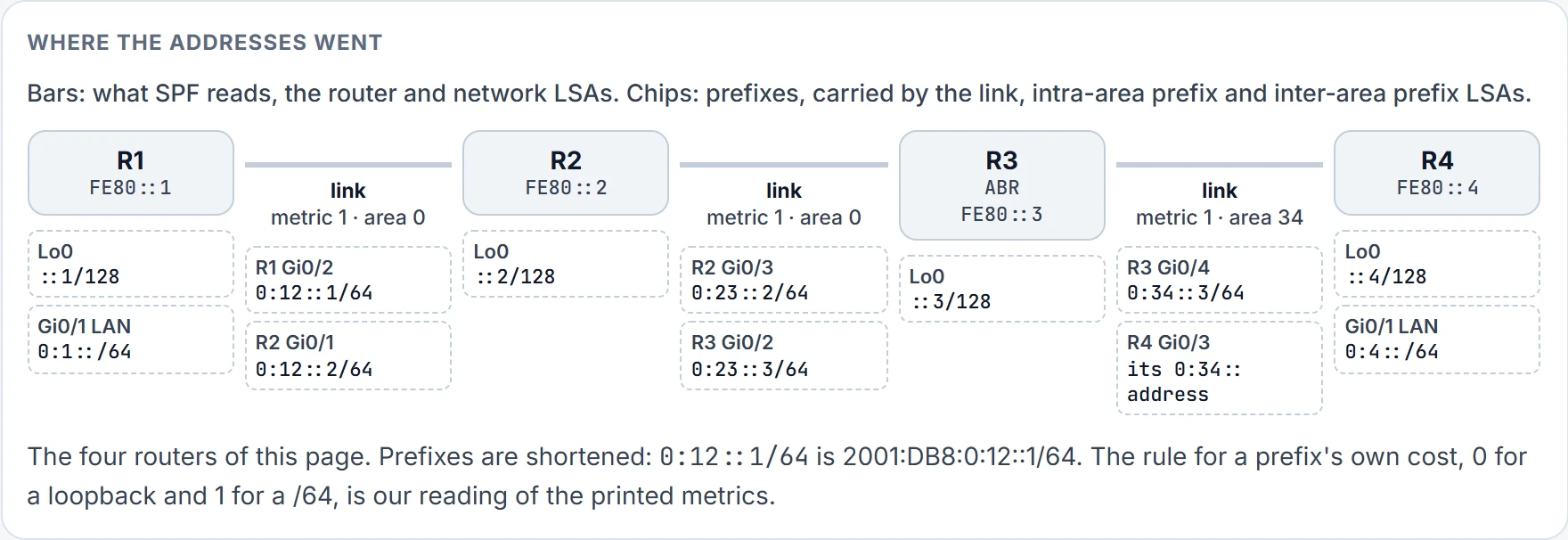
Step 1 of 9 The tree and its leaves. Three links, metric 1 each: that's everything SPF has to work with. The addresses hang underneath, one chip for each interface that has a global address.
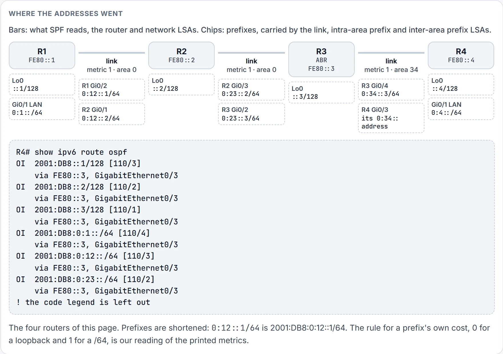
Step 2 of 9 R4's routes, before. Read a metric off the drawing: count the links to the nearest router holding the prefix, then add 0 for a loopback or 1 for a /64 on an interface. 0:12::/64 is two links to R2, plus 1: 3.
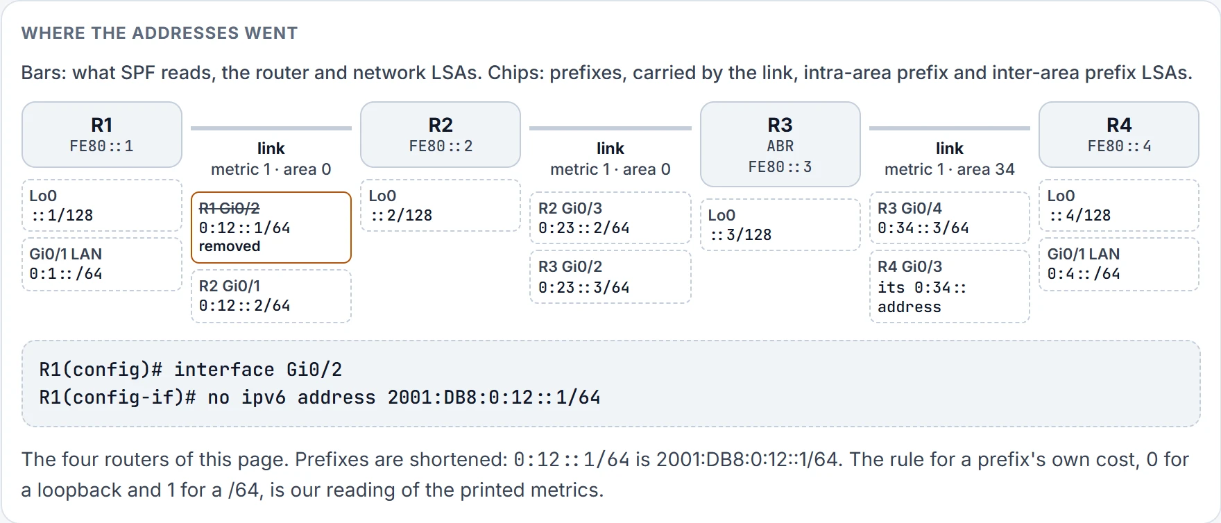
Step 3 of 9 R1, Gi0/2. One chip gone, 1 of 5. Now count the bars: still three, still metric 1. Nothing SPF reads has changed.
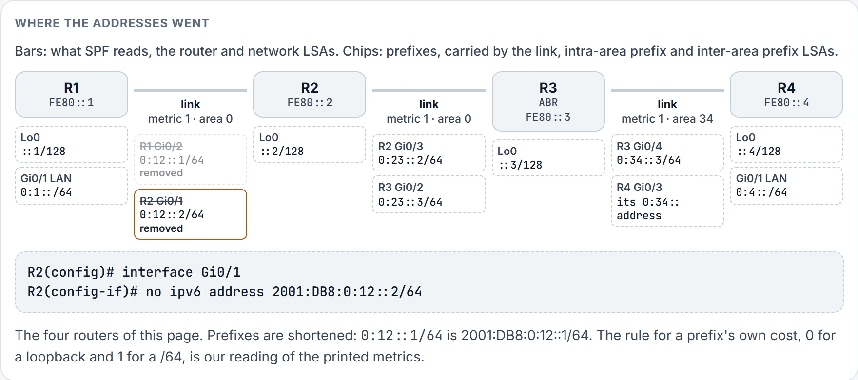
Step 4 of 9 R2, Gi0/1. One chip gone, 2 of 5. Now count the bars: still three, still metric 1. Nothing SPF reads has changed.
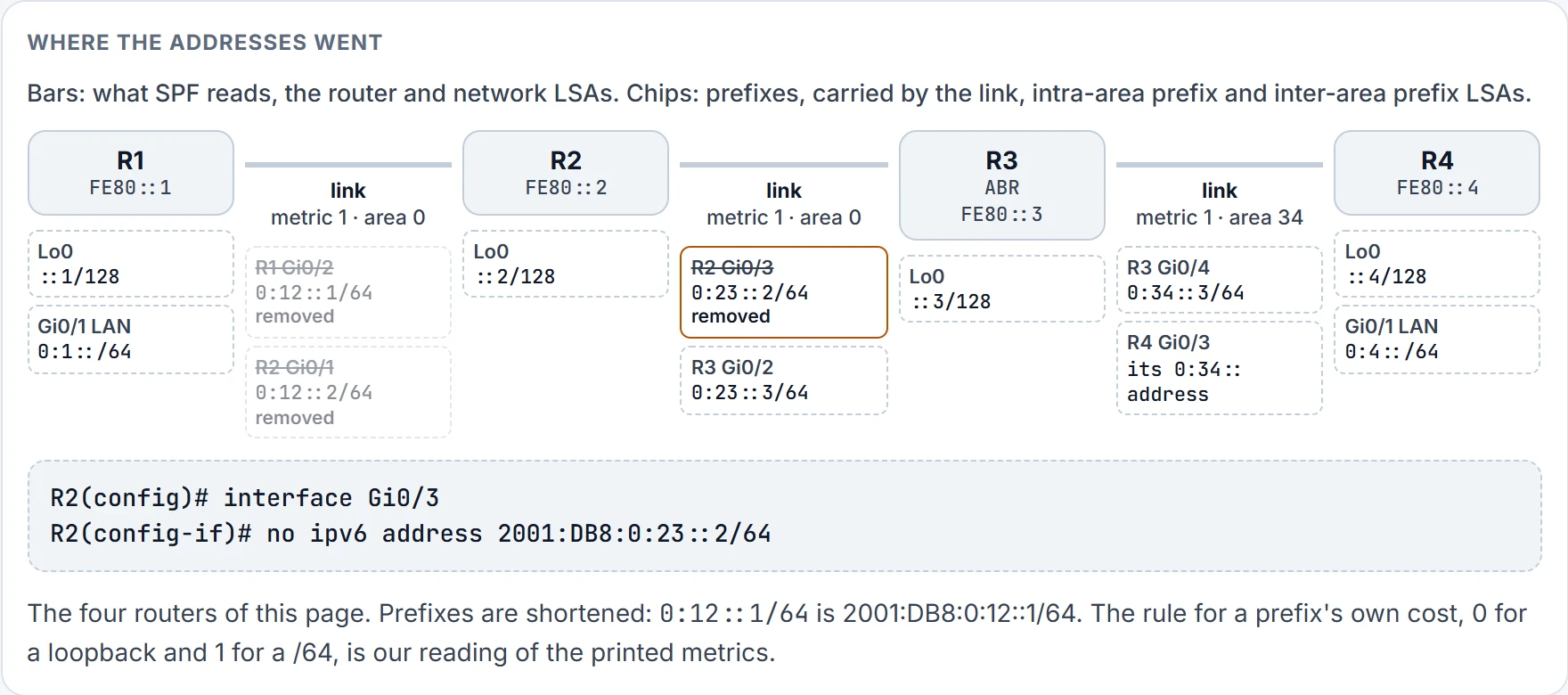
Step 5 of 9 R2, Gi0/3. One chip gone, 3 of 5. Now count the bars: still three, still metric 1. Nothing SPF reads has changed.
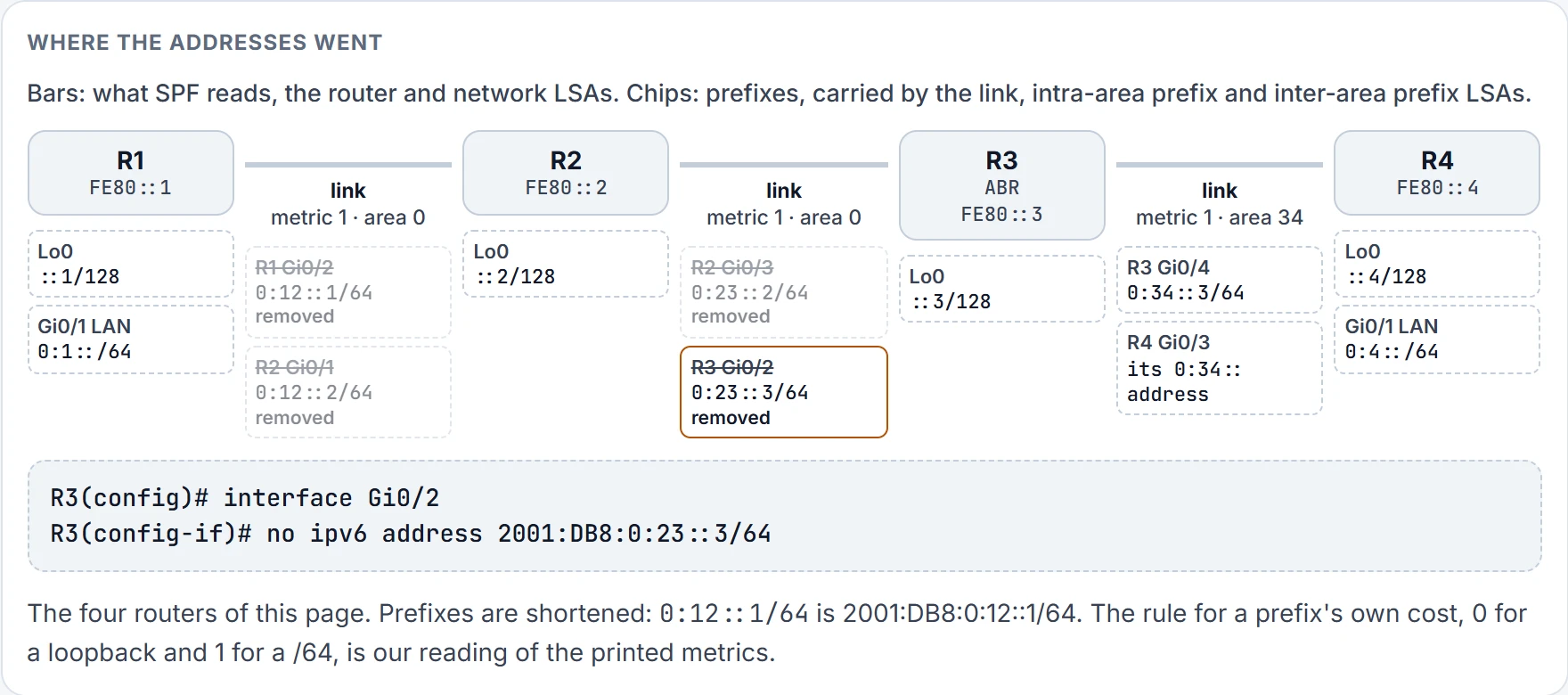
Step 6 of 9 R3, Gi0/2. One chip gone, 4 of 5. Now count the bars: still three, still metric 1. Nothing SPF reads has changed.
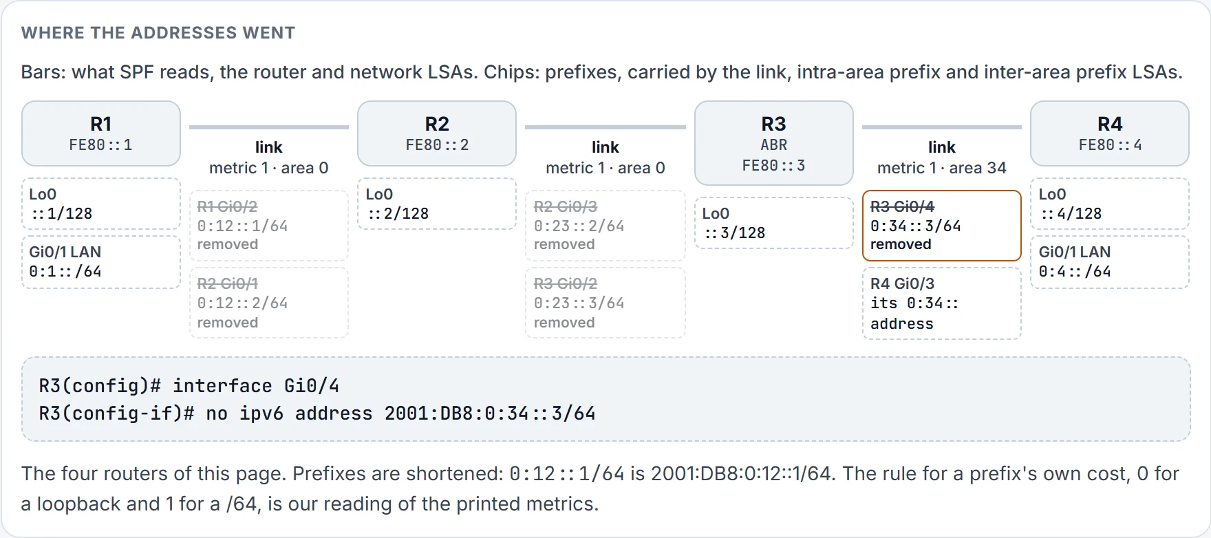
Step 7 of 9 R3, Gi0/4. One chip gone, 5 of 5. Now count the bars: still three, still metric 1. Nothing SPF reads has changed.
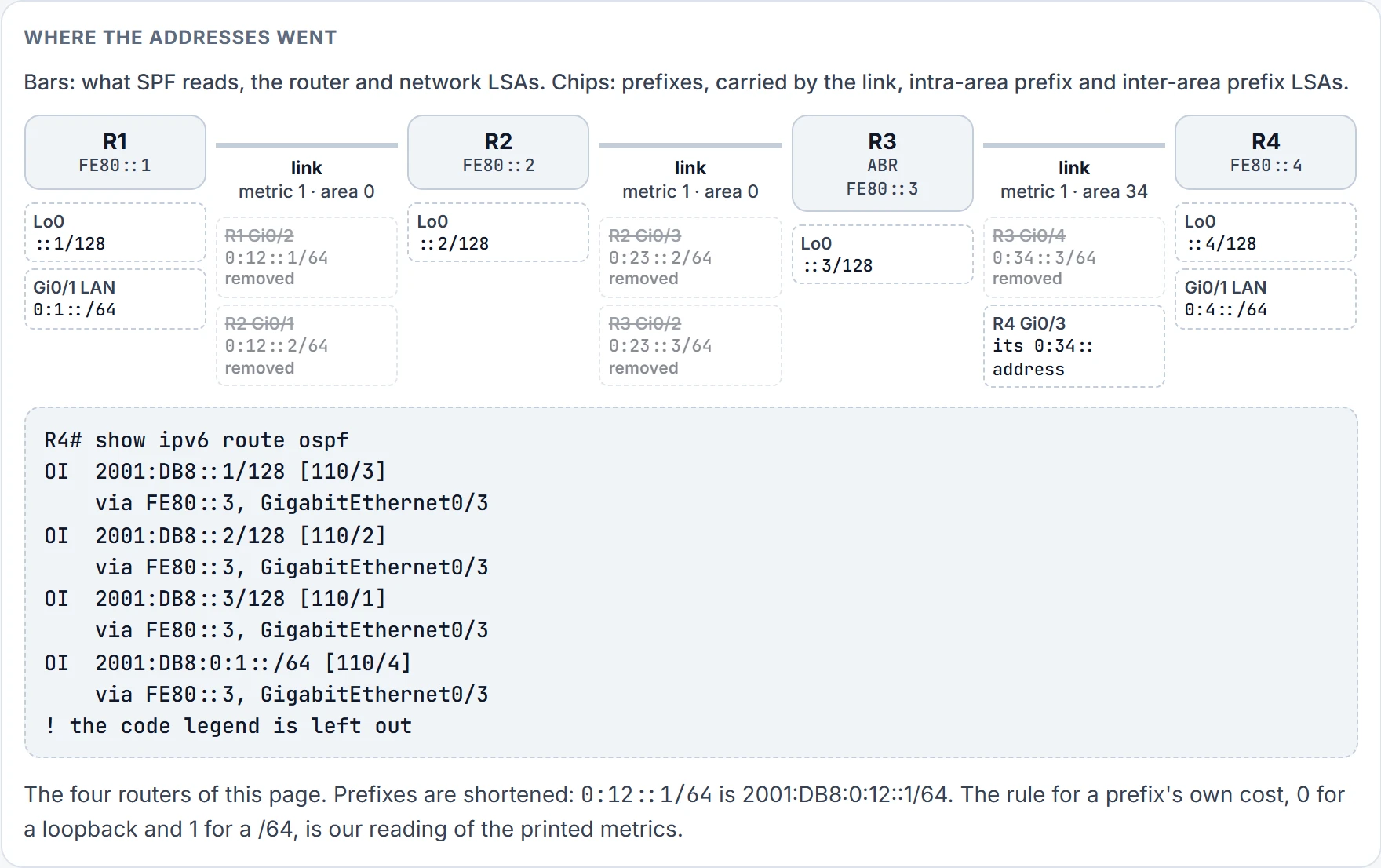
Step 8 of 9 R4's routes, after all five. The two transit /64s have gone from the table. The three loopbacks and R1's LAN are where they were: same metrics, same next hop, FE80::3.
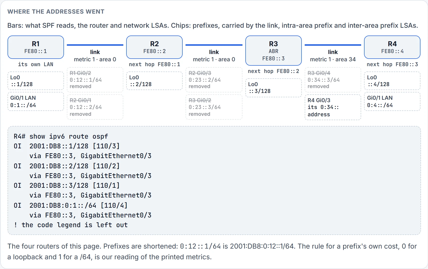
Step 9 of 9 The ping to 2001:DB8:0:1::1. R4 hands it to FE80::3. From there each router's next hop is the next link-local address along the same three links, and no link-local address was ever removed. Only R4's table is printed above; R3's and R2's next hops come from the same tree.
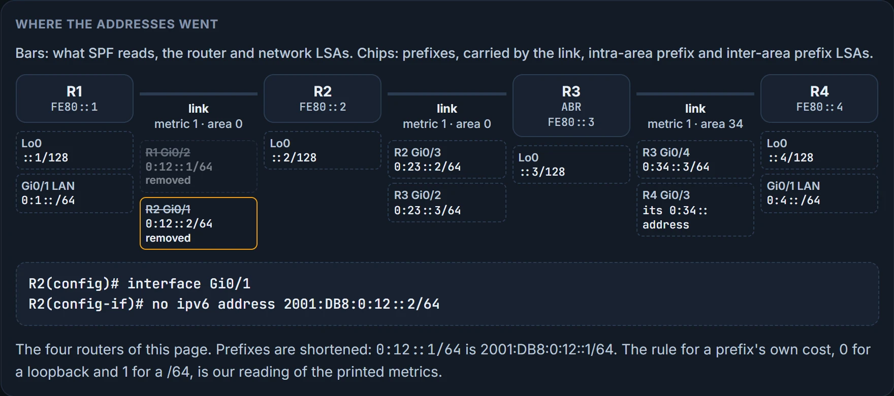
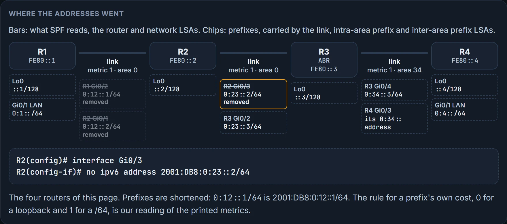
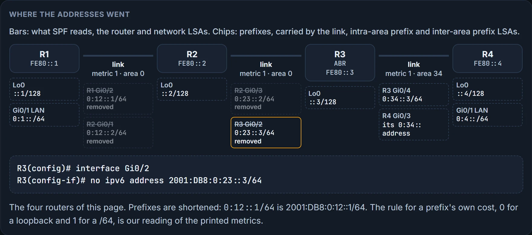
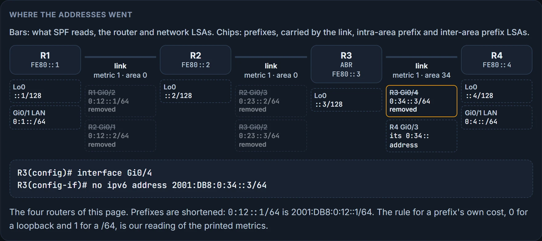
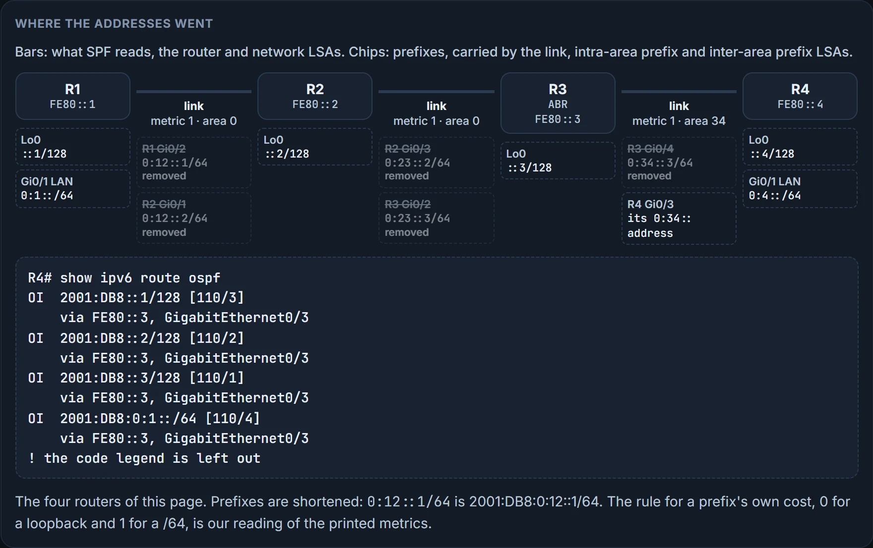
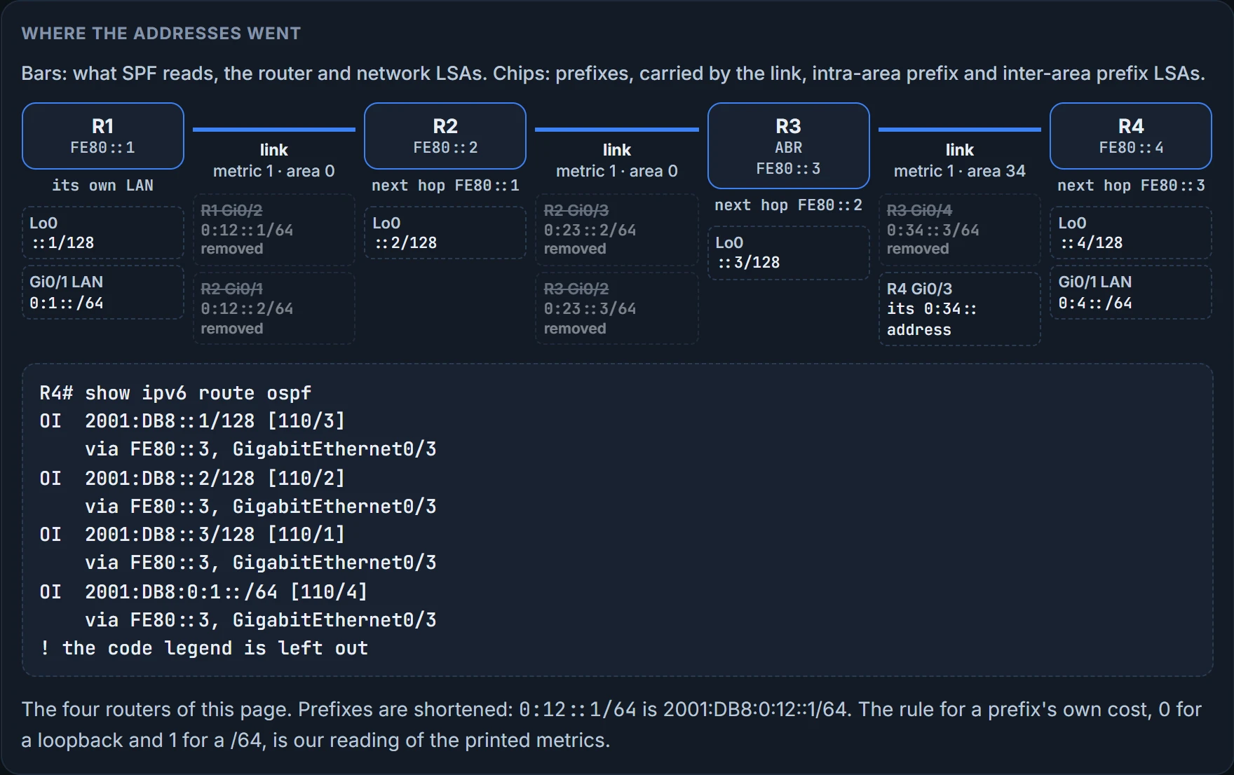
Back to the ping. Deleting the transit globals removed prefixes from link and intra-area prefix LSAs, and R3's inter-area prefix LSAs for those networks were withdrawn too, which is why R4 lost them. Nothing the SPF tree is built from, the router and network LSAs, changed, and the next hops were link-local all along.
The whole set:
| LS type | Name | Who sends it, for what |
|---|---|---|
| 0x2001 | Router (also listed as "Device" or "Device-LSA": the same LSA) | every router: the state and cost of its interfaces in the area |
| 0x2002 | Network | the DR: every router on the link, itself included |
| 0x2003 | Inter-area prefix | ABRs: prefixes in other areas |
| 0x2004 | Inter-area router | ABRs: where the ASBRs in other areas are |
| 0x4005 | AS-external | ASBRs: default routes and redistributed routes |
| 0x2007 | NSSA | ASBRs inside an NSSA: routes redistributed into the area |
| 0x0008 | Link | shared only between neighbors on the same link: a router's link-local address and the link's prefixes |
| 0x2009 | Intra-area prefix | IPv6 prefixes of a router, a stub or a transit segment |
The last two digits of each code are the LSDB lesson's numbers, 1 to 5 and 7. Types 8 and 9 are the new ones: two LSA types beyond OSPFv2's list, the link LSA and the intra-area prefix LSA, with the old types 3 and 4 renamed. Type 8 tells neighbors the link-local addresses and the IPv6 addresses on the link, so it's flooded only on the local link and never reflooded by other routers.
The ABR's view. R3 has a foot in area 0 and area 34, so it writes inter-area prefix LSAs describing routes from other areas, and show ospfv3 database gives the summary view of the whole LSDB. R3's router LSA carries the B bit for an ABR, and every inter-area prefix LSA has 192.168.3.3 as its advertising router. Area 0's section:
R3# show ospfv3 database
               Inter Area Prefix Link States (Area 0)
ADV Router       Age         Seq#        Prefix
192.168.3.3     351         0x80000002  2001:DB8:0:34::/64
               Link (Type-8) Link States (Area 0)
ADV Router       Age         Seq#        Link ID    Interface
192.168.2.2     375         0x80000002  5          Gi0/2
192.168.3.3     351         0x80000002  4          Gi0/2
               Intra Area Prefix Link States (Area 0)
ADV Router       Age         Seq#        Link ID    Ref-lstype  R…
192.168.1.1     416         0x80000003  0          0x2001      0
! router, network and more intra-area prefix rows left out; area 34 follows
This capture shows one inter-area prefix row in area 0; R1's routes above imply more, such as R4's 2001:DB8:0:4::/64. The captures were taken at different times, so don't count rows from this one.
Look at the link LSAs. R3's database holds them only from R2 and R3, the two routers on R3's Gi0/2 link. R1 wrote link LSAs too, and they're nowhere in R3's database. That's link-local flooding scope, and it's the next section.
Option bits. OSPFv3 LSAs carry an Options field describing what the router can do. Two of its bits cost you adjacencies, and you know both from the area-type lesson. The E bit says the router can process external LSAs; a router in a stubby area clears it, and neighbors with mismatched E bits don't form an adjacency. The N bit says the router supports type 7 LSAs, an NSSA, and a mismatch there stops the adjacency too: the area-type agreement rule, carried in the options as named bits. The others: V6, the router takes part in IPv6 routing; R, the router forwards traffic, and with R clear it still exchanges routes but isn't used as a transit router; DC, the router can suppress hellos on an interface configured as a demand circuit, out of scope here; MC, multicast OSPF, unused, deprecated with MOSPF by RFC 5340 in 2008. R3's router LSA, as R1 sees it, prints Area Border Router, and its Options line is worth reading too: the bits are the functionality the router can perform in each area, given per area.
Continue the lesson
The whole lesson, with its drawings and its questions. 6 more sections after the ones above.