
GRE tunnels, and the overlay/underlay split
A GRE tunnel carries packets of many protocols across an IP network by encapsulating them, with a new IP header addressed to the tunnel's far end. That splits the network in two: the underlay that carries, and the overlay that is carried. The tunnel's line protocol is up when a route to the tunnel destination exists, and a tunnel that learns that route through itself flaps.
By Arif, founder of Daveth · Updated
The full 18 min walkthrough is in Daveth Pro (Network). See what the plan opens
What this page answers
What is the difference between the overlay and underlay?
The underlay is the network that carries the tunnel: the transport addresses and their routes. The overlay is the network carried inside it: the tunnel interface's addresses and the routes learned across it. Read it in “Two networks on the same routers”
When is a GRE tunnel interface up?
Its line protocol comes up when the router finds a route to the tunnel destination in its routing table, and goes down when there is none. Up proves that route exists, not that the far end answers. Read it in “What "up" is worth”
Seven lines of log
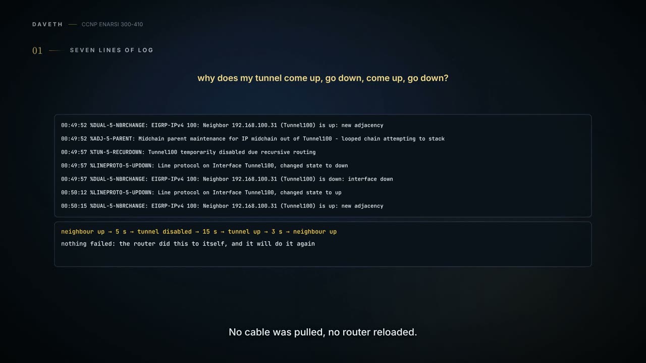
Here's one doing it. This is R11's log:
00:49:52: %DUAL-5-NBRCHANGE: EIGRP-IPv4 100: Neighbor 192.168.100.31 (Tunnel100) is up: new adjacency
00:49:52: %ADJ-5-PARENT: Midchain parent maintenance for IP midchain out of Tunnel100 - looped chain attempting to stack
00:49:57: %TUN-5-RECURDOWN: Tunnel100 temporarily disabled due recursive routing
00:49:57: %LINEPROTO-5-UPDOWN: Line protocol on Interface Tunnel100, changed state to down
00:49:57: %DUAL-5-NBRCHANGE: EIGRP-IPv4 100: Neighbor 192.168.100.31 (Tunnel100) is down: interface down
00:50:12: %LINEPROTO-5-UPDOWN: Line protocol on Interface Tunnel100, changed state to up
00:50:15: %DUAL-5-NBRCHANGE: EIGRP-IPv4 100: Neighbor 192.168.100.31 (Tunnel100) is up: new adjacency
Don't decode it yet. Look at the shape instead. A neighbor comes up. Five seconds later the router disables its own tunnel. Fifteen seconds after that the tunnel is back, and three seconds on, the neighbor is up again, which is the first line. Nothing failed. No cable was pulled, no router reloaded. The router did this to itself, and it will do it again.
There are two problems that are frequently found with tunnel or overlay networks: recursive routing and outbound interface selection. This log is the first. To read it you need to know what a tunnel is, what "up" means for one, and one rule about routing tables you already have. So leave the log here. We'll build the tunnel that produced it, and come back.
Two networks on the same routers
Start with what GRE is for. A GRE tunnel gives connectivity to a wide variety of network-layer protocols by encapsulating their packets and forwarding them over an IP-based network. Its original job was to be a transport for nonroutable legacy protocols such as DECnet, SNA and IPX. Today's job is the one this module is about: carrying one IP network across another. For the exam, the list to know: GRE tunnels support the encapsulation of DECnet, SNA, IPv4, IPv6 and MPLS, all five. (IPX belongs to the legacy sentence before this one. It isn't one of the five.)
That gives you two networks, and the lesson turns on keeping them apart in your head. A GRE tunnel is classified as an overlay network because it's built on top of an existing transport network, and that transport network is the underlay. The underlay is real cables and somebody's routers, often not yours. The overlay is what you build across it.
Here's the smallest version. Three routers in a row: R11, the provider's router SP, and R31, with a LAN behind each end, 10.1.1.0/24 and 10.3.3.0/24. The 172.16.0.0/16 range is the transport, the underlay, and 192.168.100.0/24 is used for the GRE tunnel, the overlay.
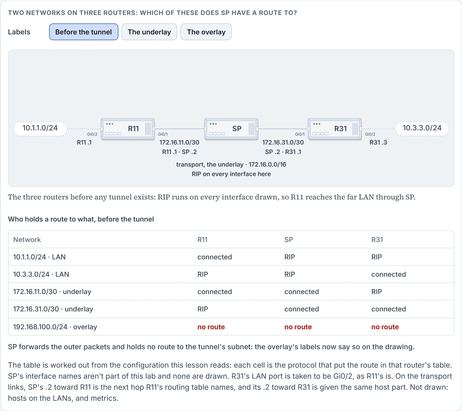
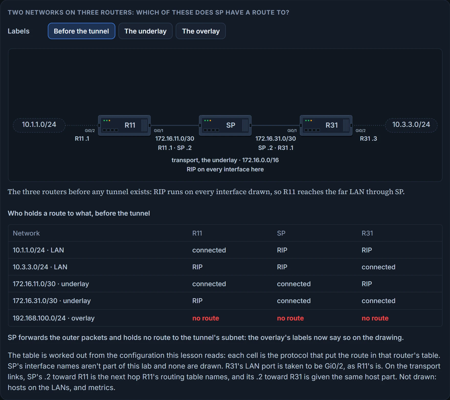
Before any tunnel exists, the three routers already route. R11, R31 and SP have RIP enabled on all their 10.0.0.0/8 and 172.16.0.0/16 interfaces, and that's what lets R11 and R31 locate the remote router's encapsulating interface, the one that adds the outer headers for the underlay and removes them from what arrives. R11 uses SP as its next hop to reach 172.16.31.0/30, and R31 uses SP toward 172.16.11.0/30. This is R11's table at that point, where 10.3.3.0/24 is reachable by RIP and is two hops away, and under it a trace from R11's LAN address to R31's:
R11# show ip route
C       10.1.1.0/24 is directly connected, GigabitEthernet0/2
R       10.3.3.0/24 [120/2] via 172.16.11.2, 00:00:01, GigabitEthernet0/1
C       172.16.11.0/30 is directly connected, GigabitEthernet0/1
R       172.16.31.0/30 [120/1] via 172.16.11.2, 00:00:10, GigabitEthernet0/1
R11# trace 10.3.3.3 source 10.1.1.1
  1 172.16.11.2 0 msec 0 msec 1 msec
  2 172.16.31.1 0 msec
Two hops in the trace as well: SP, then R31. Remember that number. The table proves which protocol owns each route on R11 and where each one points. It doesn't prove a packet gets there; the trace does that, for this one path, in one direction.
One detail looks like housekeeping and is the most important line in the section: the RIP configuration does not include the 192.168.0.0/16 range. RIP is the underlay's protocol, and it's kept away from the overlay's addresses. A later section is what happens when that separation is broken in the other direction. (It isn't kept away from the LANs. In this lab RIP runs on the 10.0.0.0/8 interfaces too, so SP knows both LANs, which is how 10.3.3.0/24 is reachable before any tunnel exists. A provider on the real internet carries no 10.x route for you.)
One thing to carry from here on. GRE and mGRE tunnels do not use encryption by default; that takes additional configuration, which is this module's last lesson. Until then, everything in the tunnel can be read by anyone on the underlay.
A packet inside a packet
What does the router actually do to a packet it sends into the tunnel? It adds header information. When the router encapsulates the packet for the GRE tunnel, the new header information contains the remote endpoint's IP address as the destination. Those new IP headers let the packet be routed between the two tunnel endpoints without anyone inspecting the packet's payload. When it reaches the remote endpoint, the GRE headers are removed and the original packet is forwarded out of the remote router.
RFC 2784 draws the result as three boxes, one on top of the next: a delivery header, then a GRE header, then the payload packet.
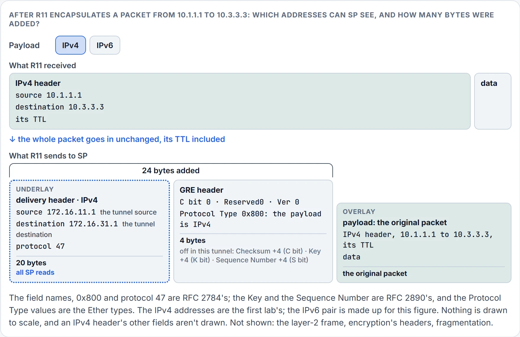
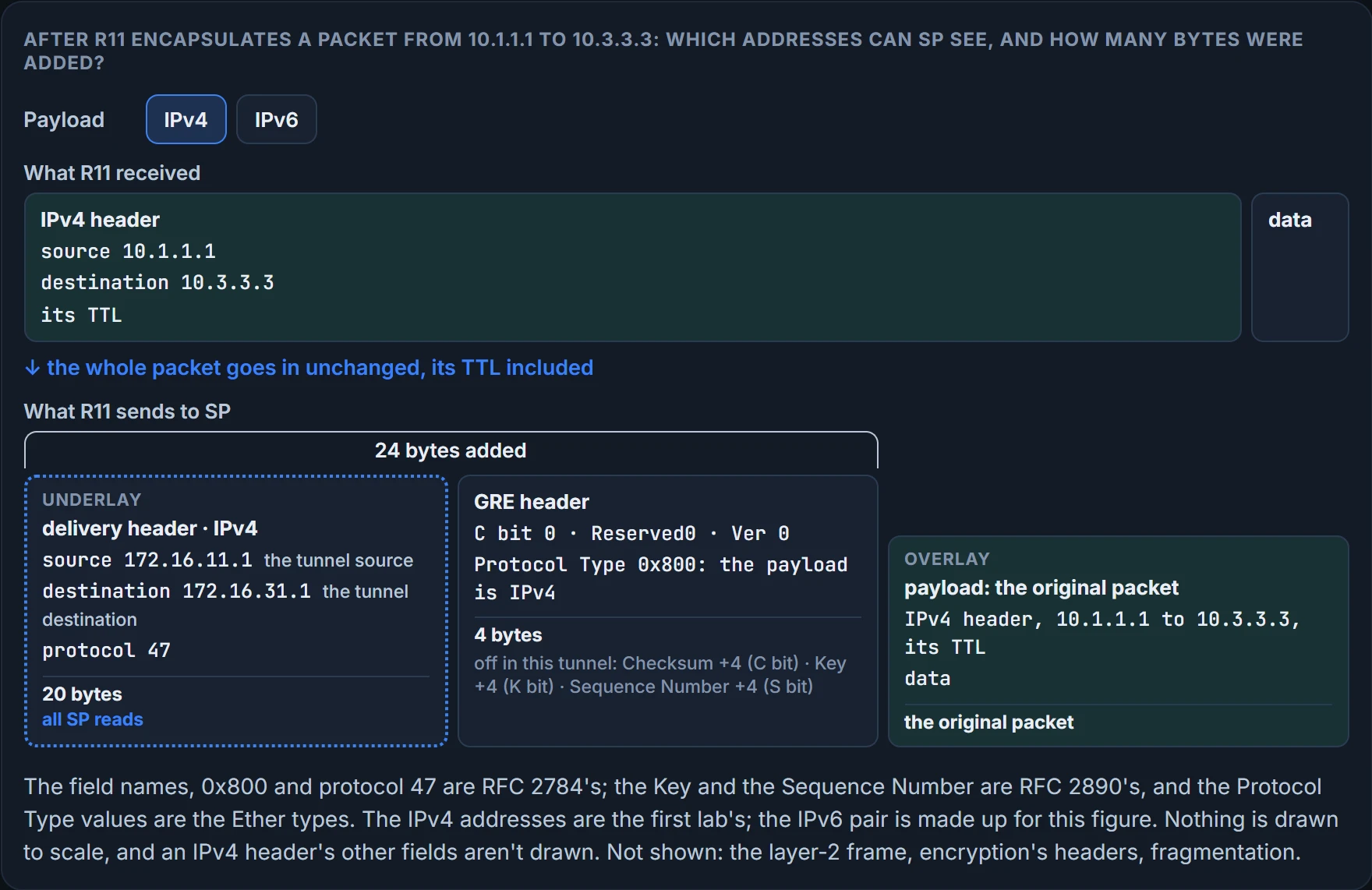
Take a packet from 10.1.1.1 to 10.3.3.3 arriving at R11. That whole packet, its own IP header included, becomes the payload. In front of it goes the GRE header, which in its basic form is one 32-bit word: a Checksum Present bit, reserved bits, a three-bit version that must be zero, and a 16-bit Protocol Type saying what the payload is, 0x800 when the payload is IPv4. In front of that goes the delivery header, an ordinary IPv4 header from 172.16.11.1 to 172.16.31.1, whose protocol field says 47, the number IPv4 uses for GRE.
It's the office's internal mail going between two buildings: the envelope marked "Accounts, desk 14" means nothing to a courier, so the mailroom puts it inside a courier envelope addressed to the other building's mailroom, and the courier reads only that. The comparison holds for exactly one thing, who reads which address, and stops there: a mailroom knows the other building's address because someone wrote it on the wall, and a router has to find its tunnel destination in a routing table, and a routing table changes. That difference is the whole of the section that reads the log.
How much bigger is the packet? The GRE tunnel adds a minimum of 24 bytes to the packet size to accommodate the headers that are added. Four of those are the GRE word you just read, which leaves 20 for the delivery header. "Minimum" is doing work. RFC 2890 adds two optional fields to the GRE header, a Key and a Sequence Number, four octets each, each switched on by its own bit, and the checksum, when present, takes four more. That's why the header size may change based on the configuration options used, and why 24 is plain GRE's figure, the one with no encryption. Encryption adds its own headers on top; this module's last lesson has those numbers.
Now the consequence you can see from a keyboard. The underlay's routers forward the outer packet and never look inside, so nothing inside changes on the way: the packet's time to live is encapsulated as part of the payload, and the original TTL decreases by only one for the GRE tunnel, regardless of the number of hops in the transport network. RFC 2784 puts the one decrement at the far end: a tunnel endpoint that decapsulates an IPv4 payload must decrement the payload's TTL.
So predict.
Not confirmed on a router, for this section: the number the Protocol Type carries for an IPv6 payload. The values are the Ether types, and 0x800 is the only one this lesson has from a source, so the figure names IPv6's without a number.
Seven steps, and which layer each one belongs to
A GRE tunnel is configured in seven steps, three of them optional. Here's R11's half of the lab's configuration, and as you read it, sort every line: is this about the network that carries, or the one that's carried?
interface Tunnel100
 bandwidth 4000
 ip address 192.168.100.11 255.255.255.0
 ip mtu 1400
 keepalive 5 3
 tunnel source GigabitEthernet0/1
 tunnel destination 172.16.31.1
interface tunnel tunnel-number, in global configuration, creates the interface. Neither layer yet; it's the box the other six lines go in.
tunnel source {ip-address | interface-id} identifies the local source: the interface that will be used for encapsulation and decapsulation of the GRE tunnel. Underlay. It can be a physical interface or a loopback, and a loopback can provide reachability if one of the transport interfaces fails. What the line settles for certain is an address: the tunnel's source address is either an explicitly defined IP address or the IP address assigned to the specified interface. Name an interface, and you've chosen the address the outer header carries as its source. So it has to be an address the underlay can route back to. Read "used for encapsulation and decapsulation" with that in mind: it tells you whose address goes on the outside. Whether it also decides which cable the outer packet leaves by is another question, and it gets a section of its own.
tunnel destination ip-address is the remote router's underlay IP address, toward which the local router sends GRE packets. Underlay again. Source and destination are the outer header, typed in.
ip address ip-address subnet-mask gives the tunnel interface its own address. Overlay. This is the first line that belongs to the network you're building, and from here a routing protocol can treat Tunnel100 like any other interface.
bandwidth, optional, in kilobits per second, range 1 to 10000000. Overlay, and it's there for the routing protocol. A virtual interface has no speed or latency of its own to measure, so you hand the router a reference bandwidth: a routing protocol that uses bandwidth to pick its best path needs a number to work with, and QoS on the interface uses the same one. On a DMVPN hub's tunnel, set 1000 or greater, and treat at least 1000 as critical if EIGRP runs over the tunnel. The EIGRP metrics lesson is why EIGRP cares.
keepalive [seconds [retries]], optional; the default timer is 10 seconds and three retries. The lab sets 5 and 3. It gets its reason in the next section.
ip mtu mtu, optional, defines the IP MTU for the tunnel interface. Overlay, and it's about those 24 bytes: specifying the IP MTU on the tunnel interface has the router perform the fragmentation in advance of the host having to detect and specify the packet MTU. Every example in this lesson sets the IP MTU to 1400. The rest of the MTU story, path MTU discovery and what happens to a packet that can't be fragmented, isn't taught here.
R31's half is the mirror: address 192.168.100.31, the same bandwidth, MTU and keepalive, source GigabitEthernet0/1, and tunnel destination 172.16.11.1, R11's transport address. Each end's destination is the other end's source. Nothing negotiates that. Two people typed it.
One line is missing, and that's deliberate. Tunnel interfaces are GRE point-to-point by default, so there's no mode to set. And notice what a point-to-point tunnel demands: a tunnel destination, at both ends, as an address known in advance. With point-to-point GRE in a hub-and-spoke network, the physical interface address of each spoke must be known when the hub is configured, because it has to be typed as the tunnel destination. The next lesson exists to remove that inconvenience.
Now the routing. The lab runs two protocols, one per layer. EIGRP is enabled on the LAN, 10.0.0.0/8, and on the tunnel network, 192.168.100.0/24; RIP is enabled on the LAN and on the transport, 172.16.0.0/16, and not on the tunnel. On R11:
router eigrp GRE-OVERLAY
 address-family ipv4 unicast autonomous-system 100
  topology base
  exit-af-topology
  network 10.0.0.0
  network 192.168.100.0
 exit-address-family
!
router rip
 version 2
 network 10.0.0.0
 network 172.16.0.0
 no auto-summary
R31's two blocks are the same, line for line. And now you know where the "EIGRP-IPv4 100" in the opening log came from: the process is named GRE-OVERLAY, and its autonomous system is 100.
Read the four network lines as the two layers. EIGRP's name 10.0.0.0 and 192.168.100.0. RIP's name 10.0.0.0 and 172.16.0.0. No EIGRP line matches a 172.16 address, so EIGRP doesn't run on GigabitEthernet0/1 and never advertises the network the tunnel's destination sits in. No RIP line matches 192.168.100.0. That is all that keeps the transport network out of the overlay's protocol: one line that isn't there. Nothing in GRE enforces it.
One network is in both lists, and that's fine. 10.0.0.0 is under both protocols, so the LANs are known to the underlay's protocol and to the overlay's. A LAN isn't a tunnel endpoint. The addresses that must stay with the underlay alone are the two the tunnel is built from, 172.16.11.1 and 172.16.31.1. (version 2 and no auto-summary are RIP's own settings, and nothing here depends on them.)
IPv6 in the overlay. The tunnel above carries IPv4 over IPv4, and it needn't: GRE tunnels support IPv4 or IPv6 addresses as an overlay or transport network. Carrying IPv6 over the same IPv4 underlay changes nothing in the outer header: you add IPv6 to the overlay. "IPv6 over IPv4" means IPv6 is the tunneled protocol over an IPv4 transport network, and the commands come in two groups, tunneled-protocol commands and transport commands, chosen separately. The tunneled-protocol group has an IPv6 twin for each IPv4 line, ipv6 mtu for ip mtu among them. And one point you must not skip. IPv6 routing protocols find their neighbors by link-local address, and install their routes with it. So a tunnel that carries IPv6 needs a link-local address, and it must be unique: that makes two address lines, for example ipv6 address FE80:100::11 link-local and a regular IPv6 address. Both the rule and that example belong to the next lesson's multipoint tunnels over an IPv6 underlay. This lesson applies the rule to one tunnel, and our point-to-point version, IPv6 and IPv4 together over IPv4, types both lines in the closing case.
The other direction, an IPv6 underlay, is where this lesson stops. For a multipoint tunnel the transport command is tunnel mode gre multipoint ipv6; the mode a point-to-point tunnel needs over an IPv6 underlay is one for this lesson's hands-on lab to record.
Not confirmed on a router, for this section: a plain tunnel's default bandwidth; what a router does with a GRE packet from a source it wasn't told to expect; that IPv6 in the overlay needs nothing more than its address lines on a default tunnel, and whether a point-to-point tunnel that has a regular IPv6 address still needs its link-local address typed; and the mode for a point-to-point tunnel over an IPv6 underlay.
What "up" is worth
Here's the rule the rest of the lesson stands on. The tunnel's line protocol enters an up state when the router detects that a route to the tunnel destination exists in the routing table; if the tunnel destination is not in the routing table, the tunnel interface's line protocol enters a down state.
So, a question: switch R31 off, and is R11's tunnel up or down?
Up. Read the rule again and notice what's absent. The far router isn't in it. The tunnel is up, and nobody checked whether anyone is at the other end. The failure-detection lesson began with a link that stays up over a dead path; here the interface is virtual, and it stays up over a destination that isn't there. The figure below has R31 switched off, and R11's tunnel still up.
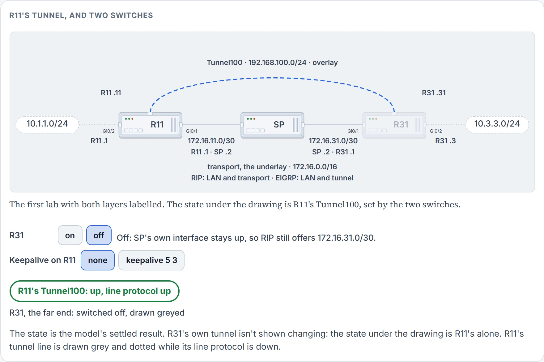
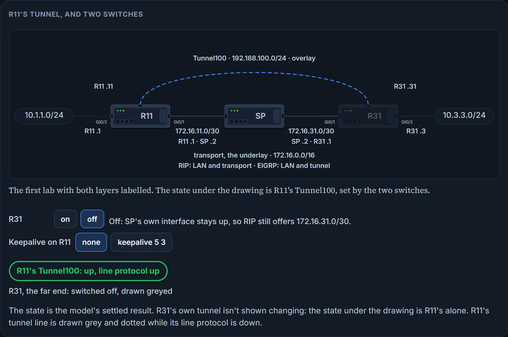
That's the job of the optional line. Tunnel keepalives ensure that bidirectional communication exists between the tunnel endpoints to keep the line protocol up; otherwise, the router must rely on routing protocol timers to detect a dead remote endpoint. With keepalive 5 3 on R11, the tunnel goes down when R31 does. One warning before you make it a habit: GRE tunnel keepalives are not supported on point-to-point or multipoint GRE tunnels in a DMVPN network. They belong to the plain tunnel of this lesson, and a later lesson in this module has what DMVPN uses in their place.
Verify the tunnel with show interface tunnel number. Four things to find in its output: the tunnel source and destination addresses, the keepalive values if any, the tunnel line protocol state, and the fact that the tunnel is a GRE/IP tunnel. On R11:
R11# show interface tunnel 100
! Output omitted for brevity
Tunnel100 is up, line protocol is up
  Hardware is Tunnel
  Internet address is 192.168.100.1/24
  MTU 17916 bytes, BW 400 Kbit/sec, DLY 50000 usec,
    reliability 255/255, txload 1/255, rxload 1/255
 Encapsulation TUNNEL, loopback not set
 Keepalive set (5 sec), retries 3
 Tunnel source 172.16.11.1 (GigabitEthernet0/1), destination 172.16.31.1
 Tunnel Subblocks:
    src-track:
       Tunnel100 source tracking subblock associated with GigabitEthernet0/1
      Set of tunnels with source GigabitEthernet0/1, 1 member (includes
      iterators), on interface <OK>
 Tunnel protocol/transport GRE/IP
    Key disabled, sequencing disabled
    Checksumming of packets disabled
 Tunnel TTL 255, Fast tunneling enabled
 Tunnel transport MTU 1476 bytes
 Tunnel transmit bandwidth 8000 (kbps)
 Tunnel receive bandwidth 8000 (kbps)
 Last input 00:00:02, output 00:00:02, output hang never
Start with the four. "Tunnel100 is up, line protocol is up" is the state, and by the rule above it means a route. "Keepalive set (5 sec), retries 3" is the configuration's keepalive 5 3. "Tunnel source 172.16.11.1 (GigabitEthernet0/1)" is the outer header's source: the address first, and in brackets the interface you named. "destination 172.16.31.1" is the outer header's destination. Both are underlay addresses, and this is the line to read first on any tunnel that isn't working. "GRE/IP" is the tunnel protocol over its transport.
Next, the lines you can already explain. "Key disabled, sequencing disabled" and "Checksumming of packets disabled" are the three optional fields, all off, so this tunnel's GRE header is the four-byte one. "Tunnel transport MTU 1476 bytes" is 1500 less the 24. "Internet address is 192.168.100.1/24" is where this command prints the tunnel's own address, the overlay's. The address is 192.168.100.11, as configured; read .1 here as that. Likewise "BW 400 Kbit/sec" is where the bandwidth line shows, and the configured figure is 4000.
That leaves lines this lesson doesn't use, and two things not to do with them. Don't mix up the MTU figures: this one output carries two, 17916 on the line every interface prints and 1476 near the bottom, and the 1400 you typed as ip mtu is a third that isn't among these lines. Three different things. And don't read "Tunnel transmit bandwidth 8000 (kbps)" and "Tunnel receive bandwidth 8000 (kbps)" as the bandwidth line's 4000: they are two more bandwidth figures, printed among the tunnel's own parameters.
What does it prove? That the tunnel is configured the way you think, between these two addresses, and that this router has a route to the destination; with a keepalive set, that the far end answered. What doesn't it prove? Without a keepalive, anything at all about the far end. And never that a routing protocol inside the tunnel has a neighbor, or that a single route crossed it. Three commands from this lesson to know from memory, in exactly these forms: tunnel source {ip-address | interface-id}, tunnel destination ip-address and show interface tunnel number.
For neighbors and routes you read the routing table. R11 and R31 become direct EIGRP peers on the GRE tunnel, because all the network traffic is encapsulated between them: SP forwards their hellos inside GRE and never sees them. This is R11's table afterwards, and R11 now learns 10.3.3.0/24 directly from R31 through tunnel 100:
C     10.1.1.0/24 is directly connected, GigabitEthernet0/2
D     10.3.3.0/24 [90/38912000] via 192.168.100.31, 00:03:35, Tunnel100
C     172.16.11.0/30 is directly connected, GigabitEthernet0/1
R     172.16.31.0/30 [120/1] via 172.16.11.2, 00:00:03, GigabitEthernet0/1
C     192.168.100.0/24 is directly connected, Tunnel100
10.3.3.0/24 was a RIP route before the tunnel. RIP still offers it; both protocols cover 10.0.0.0/8. But EIGRP has the lower administrative distance, 90, so the routers use the route learned from the EIGRP connection, through the GRE tunnel, and not the one learned from RIP, 120, that came from the transport network. That's the routing table lesson's rule, doing what you wanted.
Now look at the line under it, because it's the one keeping the tunnel alive. 172.16.31.0/30, the network the tunnel destination sits in, is still RIP's, still via 172.16.11.2, still out of GigabitEthernet0/1. The overlay took the LAN route. The underlay kept the route to the tunnel's far end. Two layers, each with its own protocol, and the table shows it.
And your prediction about the trace:
R11# traceroute 10.3.3.3 source 10.1.1.1
 1 192.168.100.31 1 msec * 0 msec
One line, and the address on it is R31's tunnel address. From R11's perspective the network is only one hop away, and the traceroute doesn't display the hops in the underlay. SP forwarded every one of those probes and doesn't appear, because SP never saw their TTL. A trace across a tunnel proves the overlay's path. It doesn't prove anything about the underlay's, and it can't show you where in the underlay a problem is.
Not confirmed on a router, for this section: how a router counts the keepalive's retries; what the BW field prints for a configured bandwidth; and where 17916, the source-tracking block, the tunnel's TTL of 255 and the two 8000 figures come from, or what the router does with them.
The tunnel that pulls its own rug out
Back to the log. You now hold two of the three rules it runs on: the lower administrative distance wins a prefix, and the tunnel's line protocol follows the route to the tunnel destination. The third is in this section.
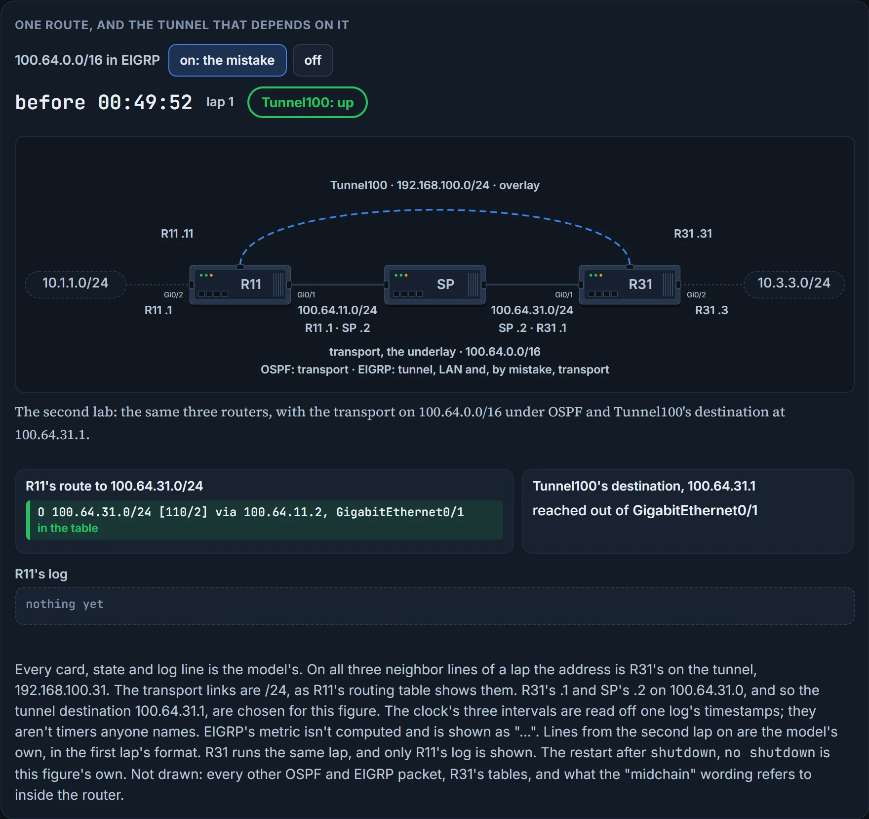
The log comes from a second lab. Same three routers, same LANs, same tunnel network, but the transport is now 100.64.0.0/16, and R11, R31 and the SP routers run OSPF on it; R11 and R31 run EIGRP on the 10.0.0.0/8 LAN and the 192.168.100.0/24 tunnel network. This is R11's table with everything working:
C        10.1.1.0/24 is directly connected, GigabitEthernet0/2
D        10.3.3.0/24 [90/25610240] via 192.168.100.31, 00:02:35, Tunnel0
C        100.64.11.0/24 is directly connected, GigabitEthernet0/1
O        100.64.31.0/24 [110/2] via 100.64.11.2, 00:03:11, GigabitEthernet0/1
C        192.168.100.0/24 is directly connected, Tunnel100
The same picture as before: the LAN route is the overlay's, D, and the route to the far end's transport network, 100.64.31.0/24, is the underlay's, O, at distance 110. (The D route's exit is Tunnel100, the tunnel on the last line; read Tunnel0 as that.)
Then the warning. It's important to be careful when using a routing protocol on a network tunnel: if a router tries to reach the remote router's encapsulating interface, its transport IP address, through the tunnel, problems will occur. And here is how that usually comes about: it's a common issue when a transport network is advertised into the same routing protocol that runs on the overlay network.
Here it comes about like this. A junior network administrator accidentally adds the 100.64.0.0/16 network interfaces to EIGRP on R11 and R31. The SP router isn't running EIGRP, so no adjacency forms with it, but R11 and R31 add the transport network to EIGRP, which has a lower AD (administrative distance) than OSPF. In configuration terms that's one more network line under EIGRP's address family, one that matches the 100.64 interfaces.
Stop there and predict, before the figure runs.
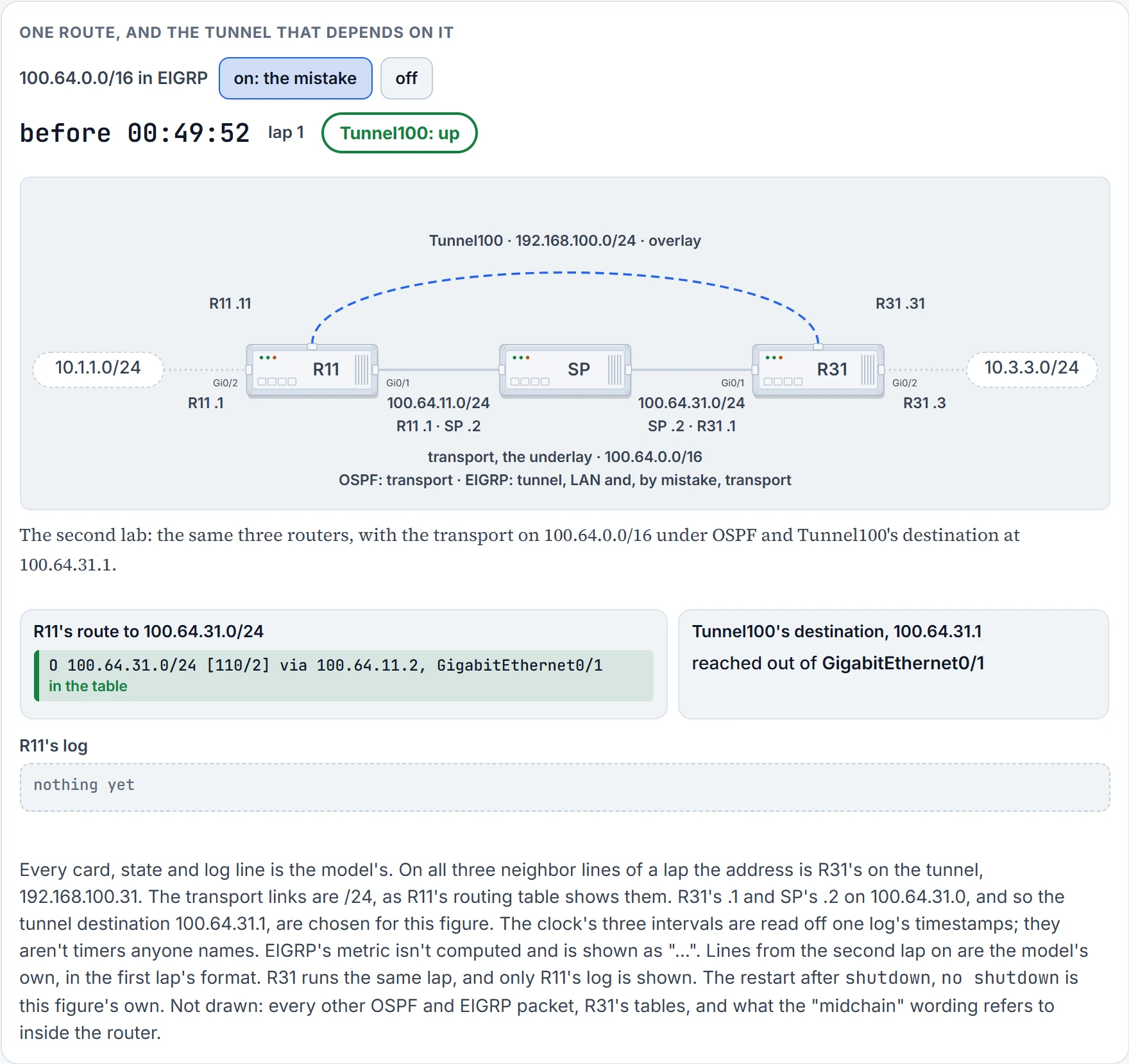
Step 1 of 12 Tunnel100 is up: R11 holds a route to 100.64.31.1, it's OSPF's, and it leaves by GigabitEthernet0/1. No EIGRP neighbor on the tunnel yet.
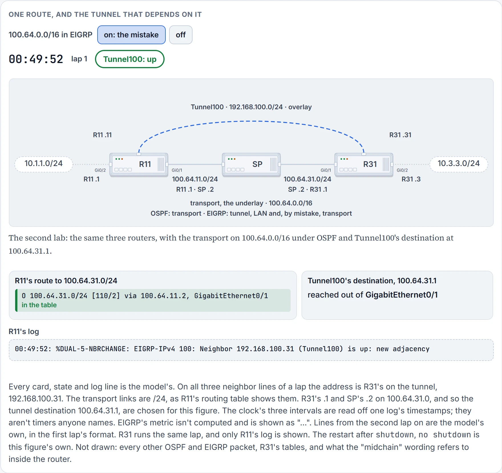
Step 2 of 12 EIGRP forms its adjacency across the tunnel. It looks like good news.
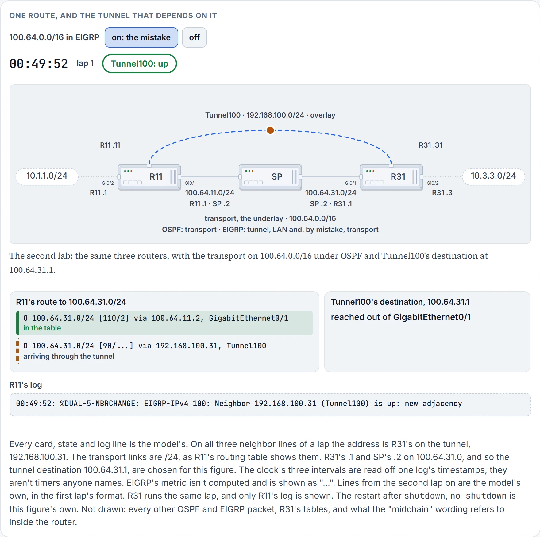
Step 3 of 12 With the adjacency comes R31's EIGRP update for 100.64.31.0/24, the transport network somebody added to EIGRP. It arrives through the tunnel.
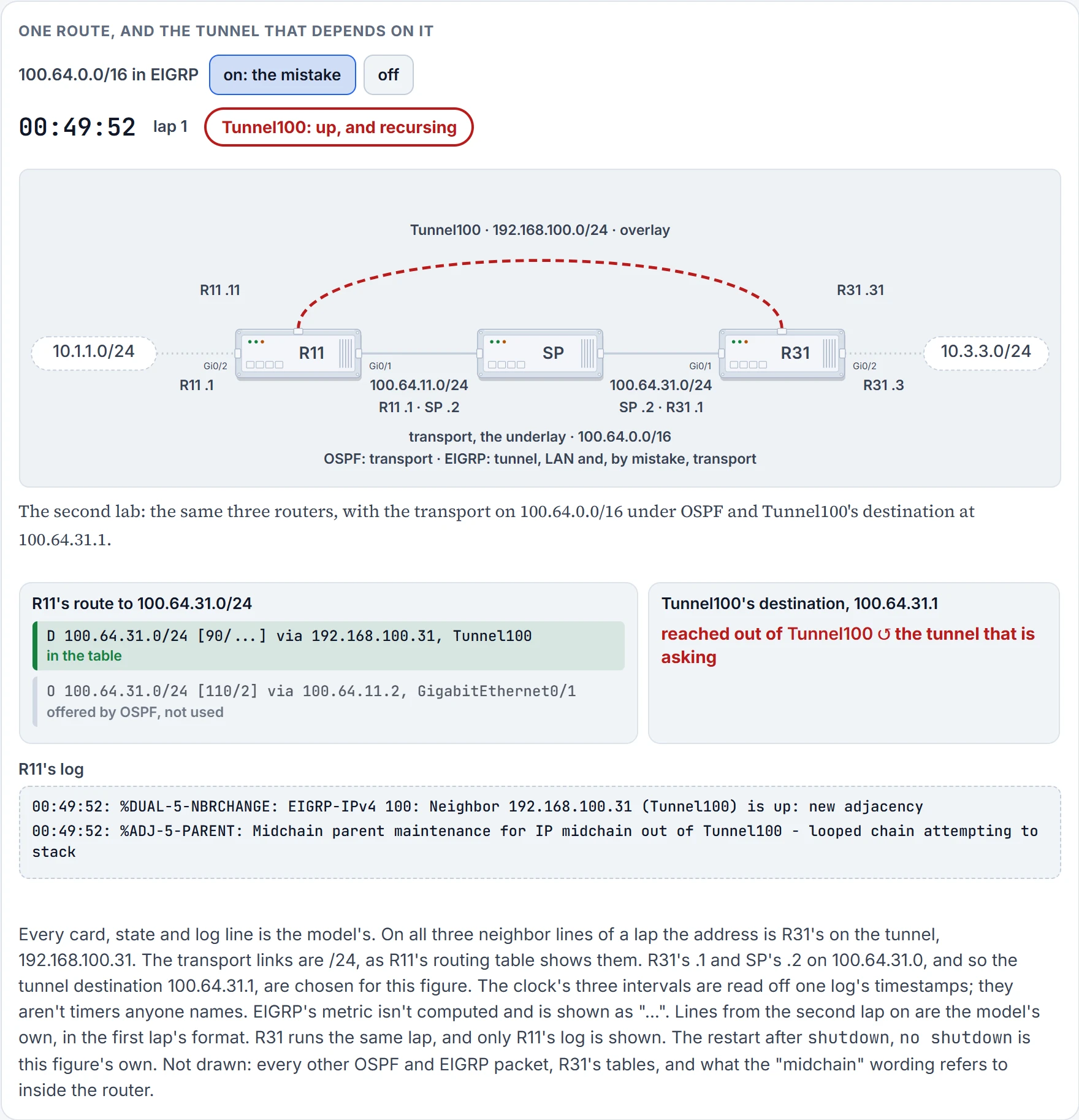
Step 4 of 12 EIGRP's 90 beats OSPF's 110, so the D route goes in, and R11's route to the tunnel's own destination now leaves by Tunnel100. That's recursive routing, and the router says so.
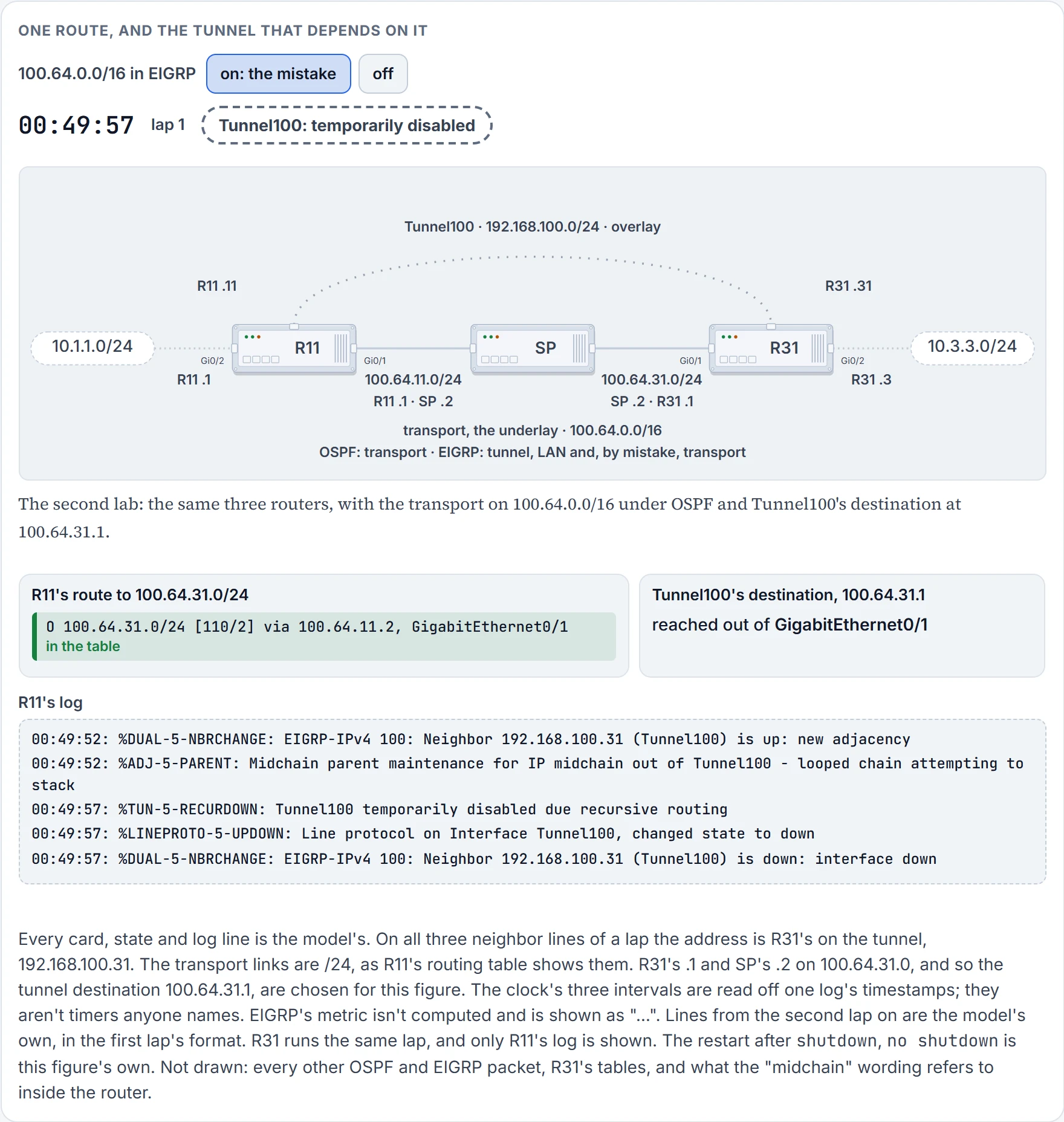
Step 5 of 12 Five seconds on in this log, the router disables its own tunnel. The neighbor goes, and its routes go with it. Nothing has happened to OSPF, so its route is the best one again in this same second, out of GigabitEthernet0/1. The tunnel stays disabled all the same.
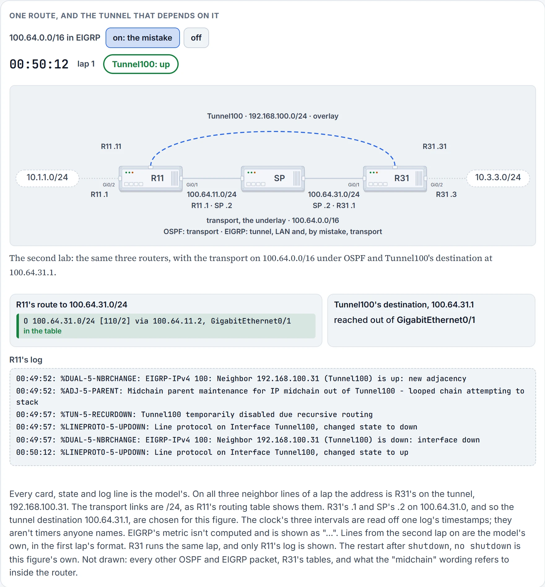
Step 6 of 12 Fifteen seconds on in this log, the line protocol comes back. Neither card changes: the outside route was already there. The route to the destination leaves by GigabitEthernet0/1, so nothing stops the tunnel coming up.
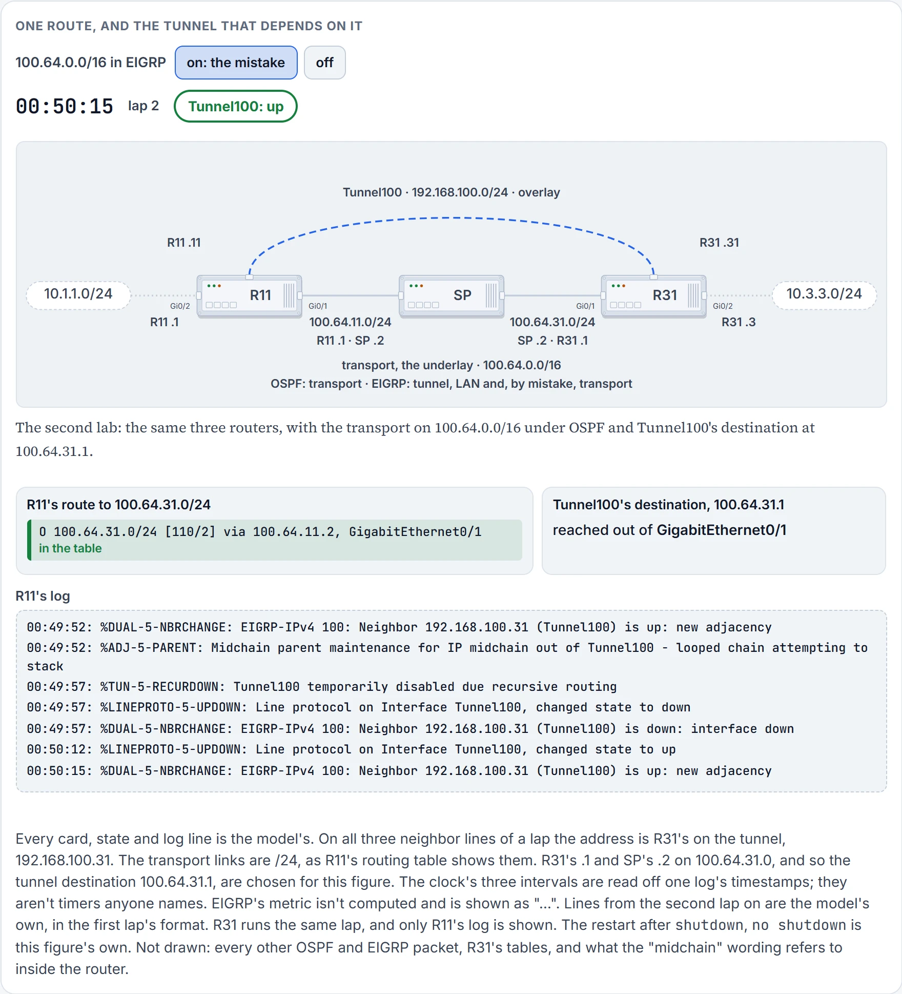
Step 7 of 12 The neighbor is up again. That's the log's first line, and lap 2 begins.
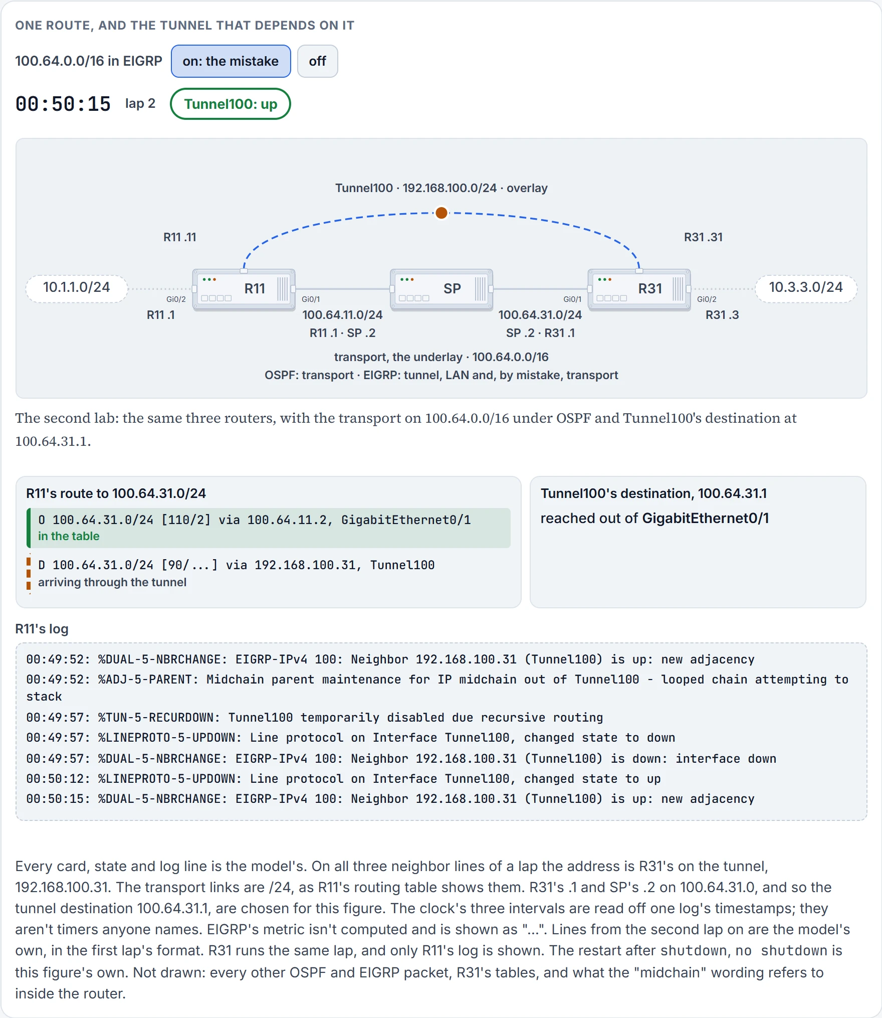
Step 8 of 12 With the adjacency comes R31's EIGRP update for 100.64.31.0/24, the transport network somebody added to EIGRP. It arrives through the tunnel.
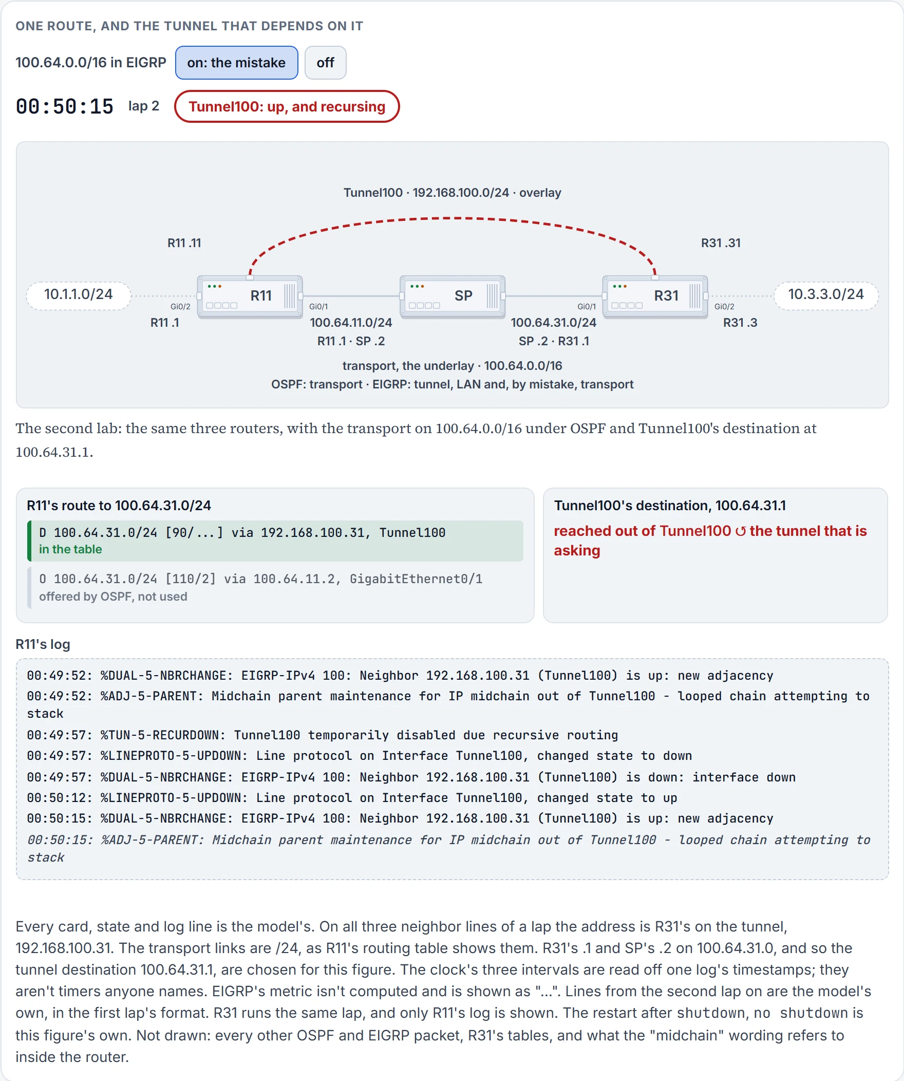
Step 9 of 12 EIGRP's 90 beats OSPF's 110, so the D route goes in, and R11's route to the tunnel's own destination now leaves by Tunnel100. That's recursive routing, and the router says so.
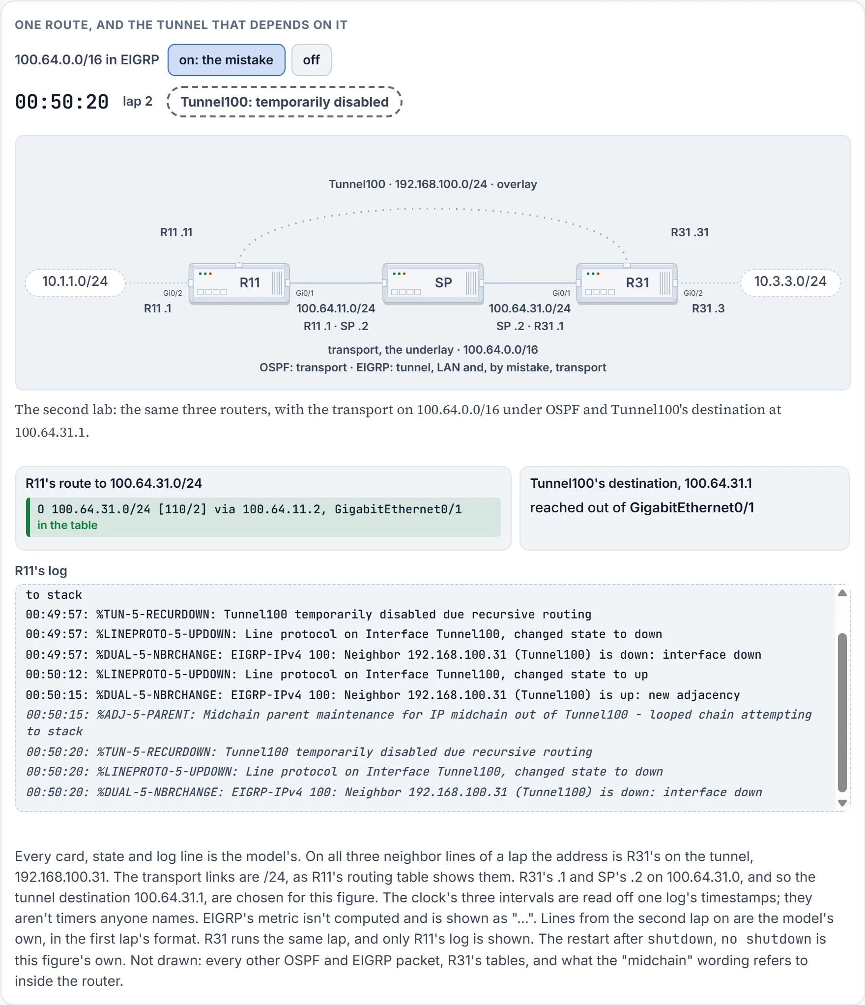
Step 10 of 12 Five seconds on in this log, the router disables its own tunnel. The neighbor goes, and its routes go with it. Nothing has happened to OSPF, so its route is the best one again in this same second, out of GigabitEthernet0/1. The tunnel stays disabled all the same.
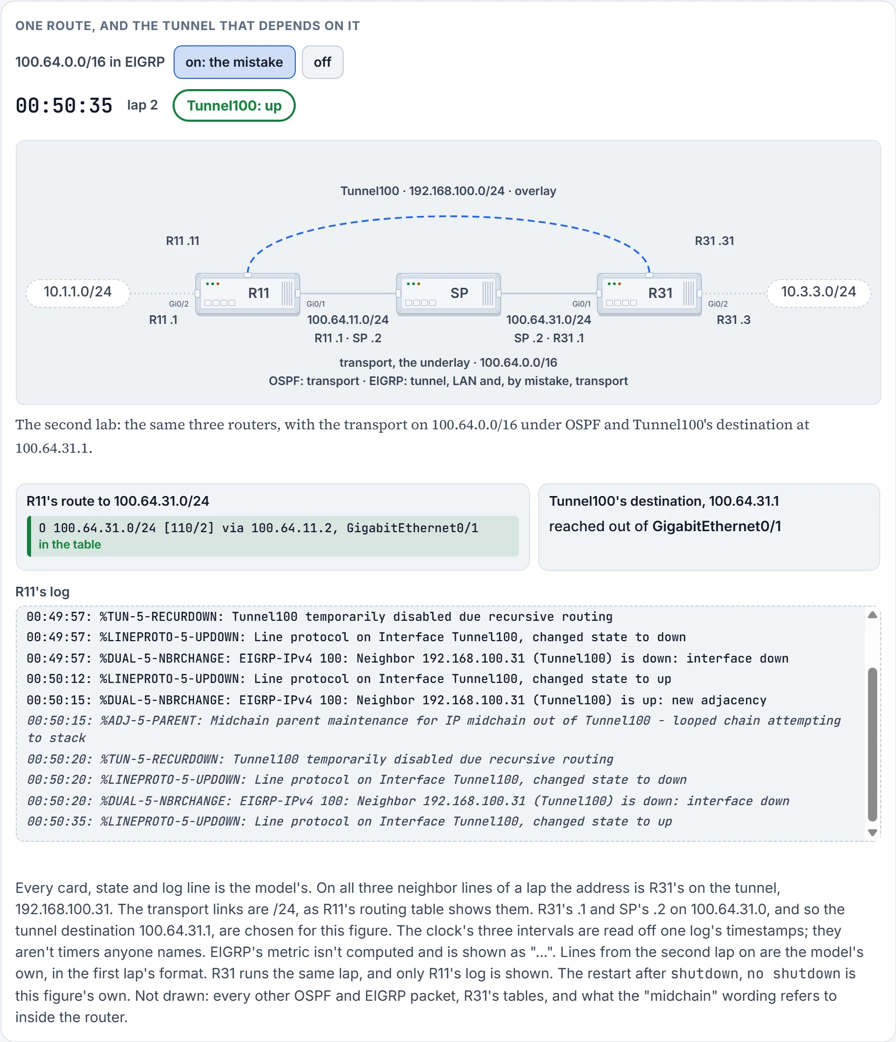
Step 11 of 12 Fifteen seconds on in this log, the line protocol comes back. Neither card changes: the outside route was already there. The route to the destination leaves by GigabitEthernet0/1, so nothing stops the tunnel coming up.
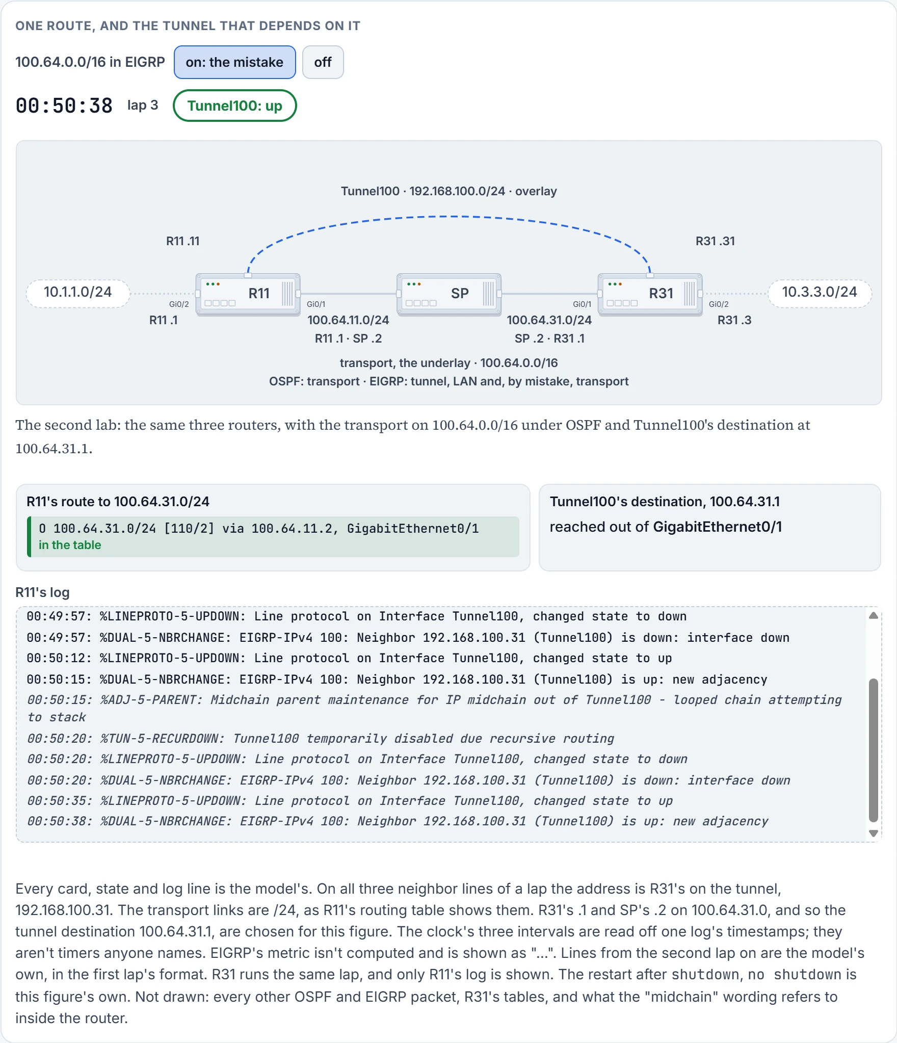
Step 12 of 12 The neighbor is up again. That's the log's first line, and lap 3 begins.
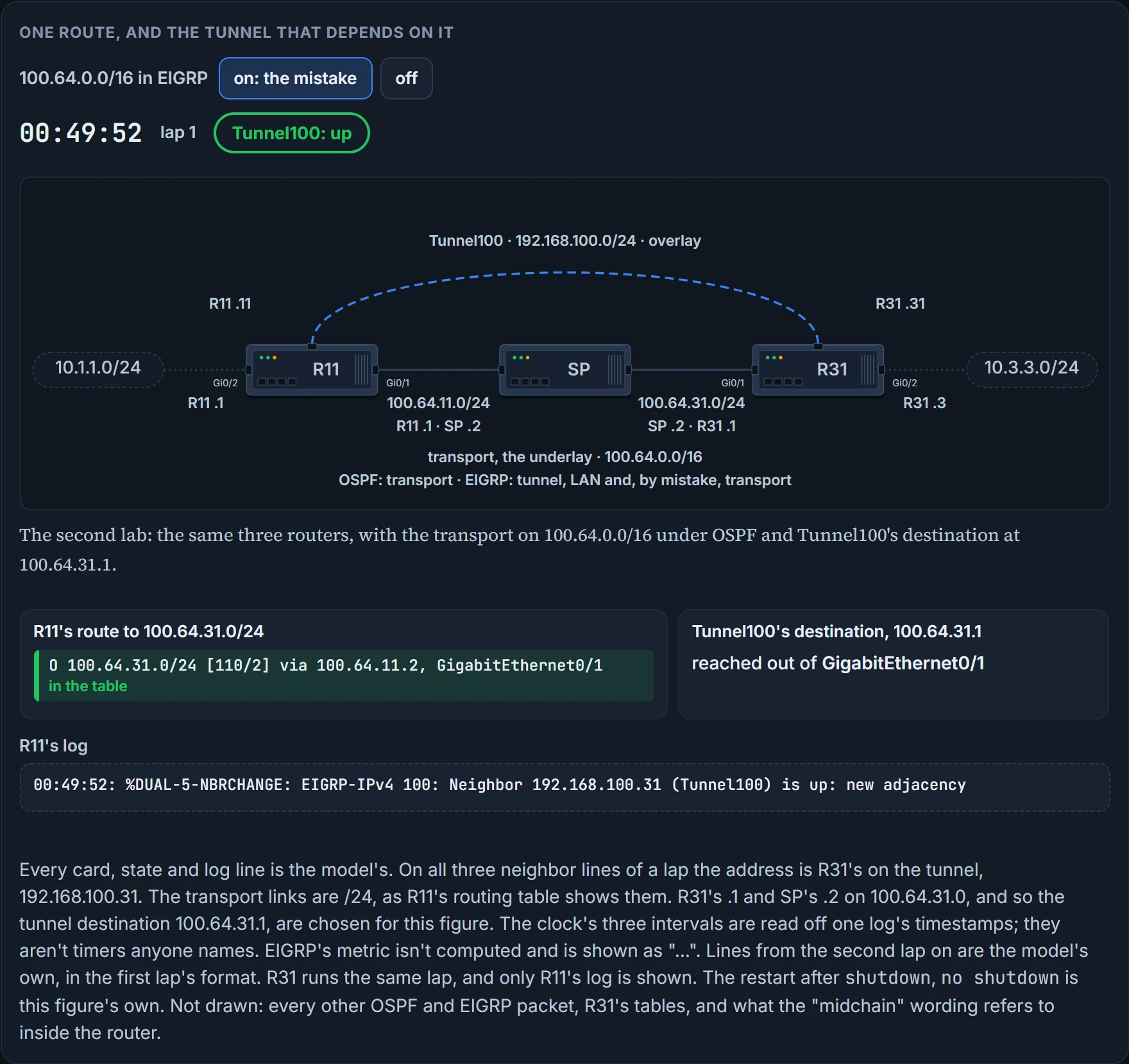
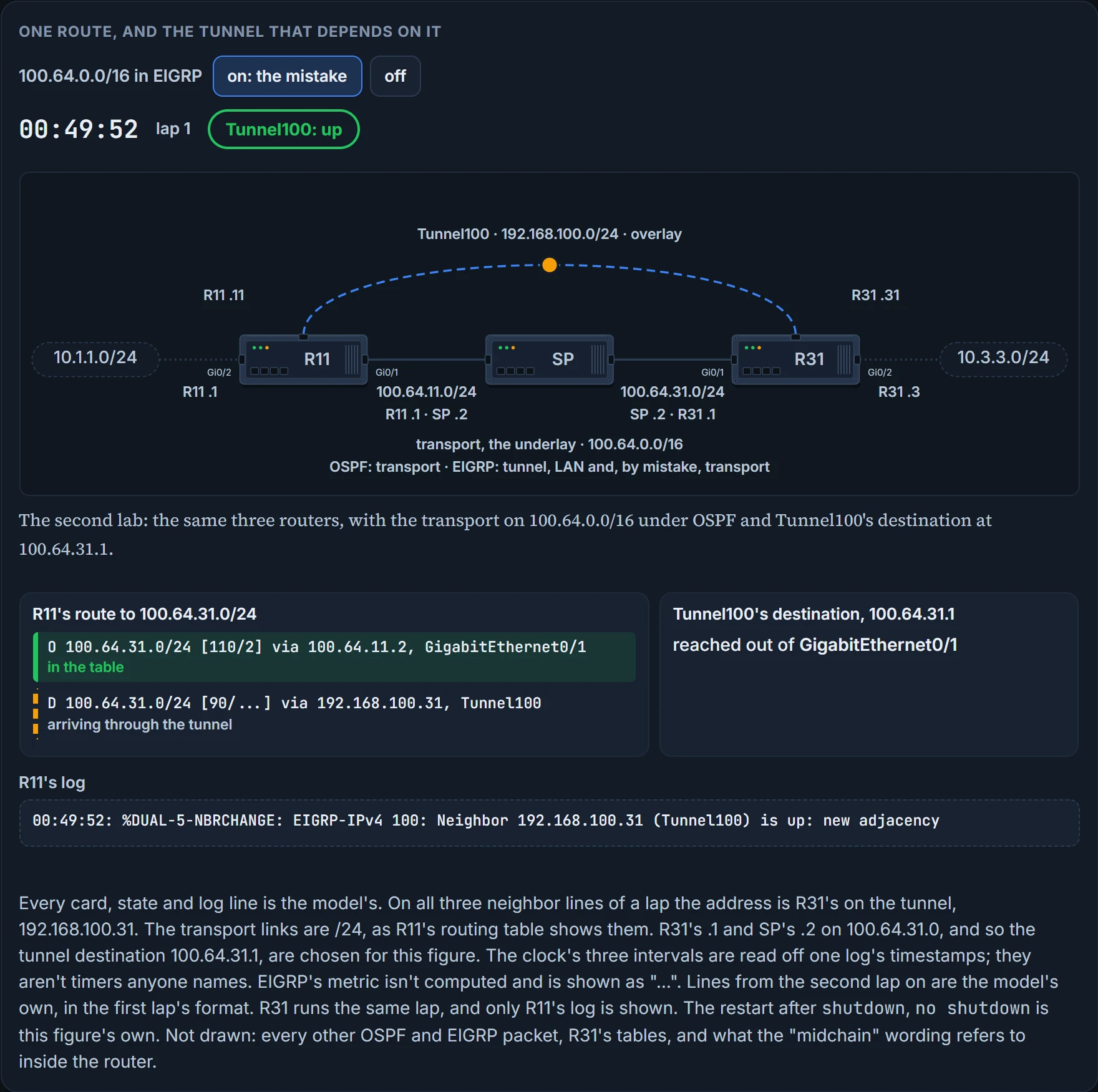
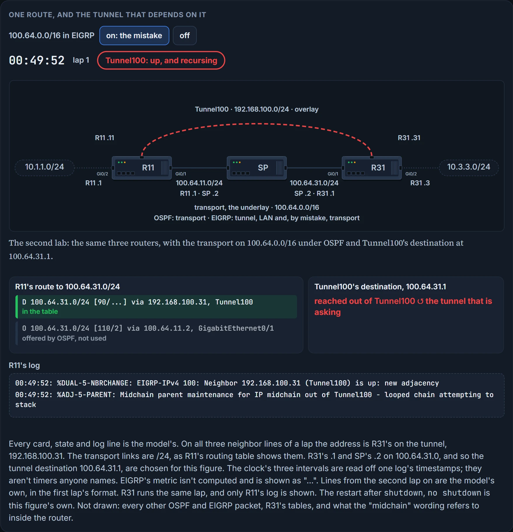
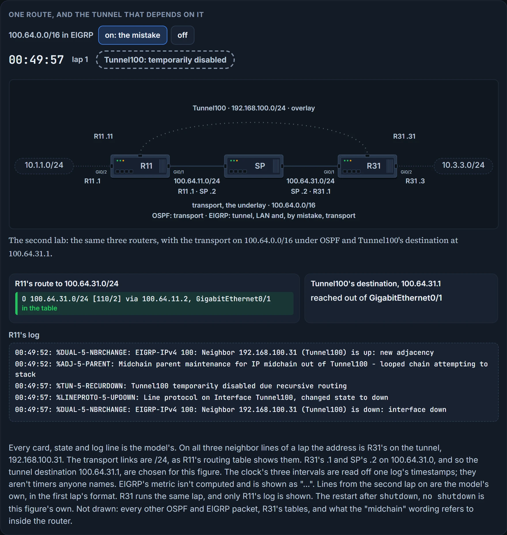
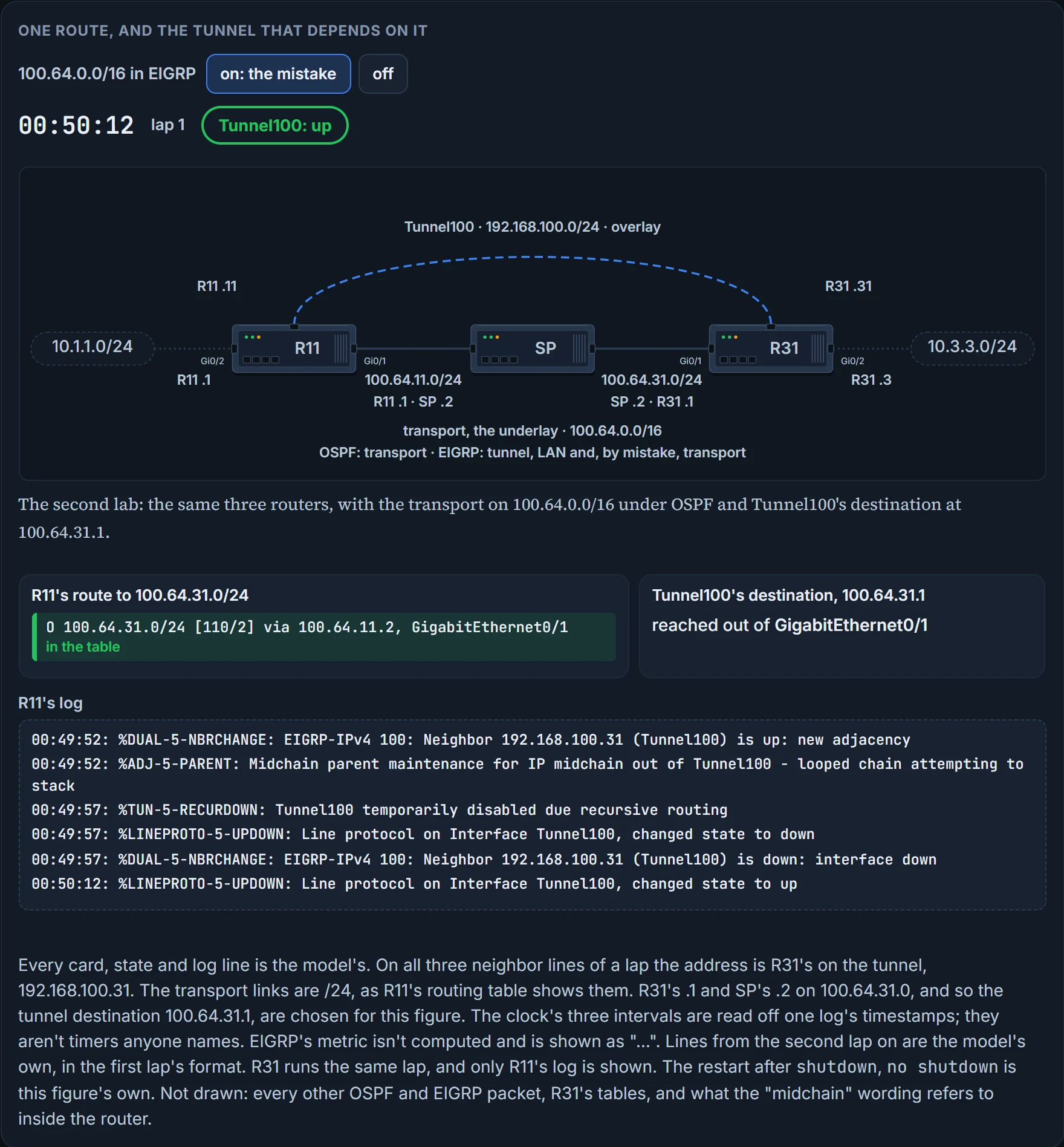
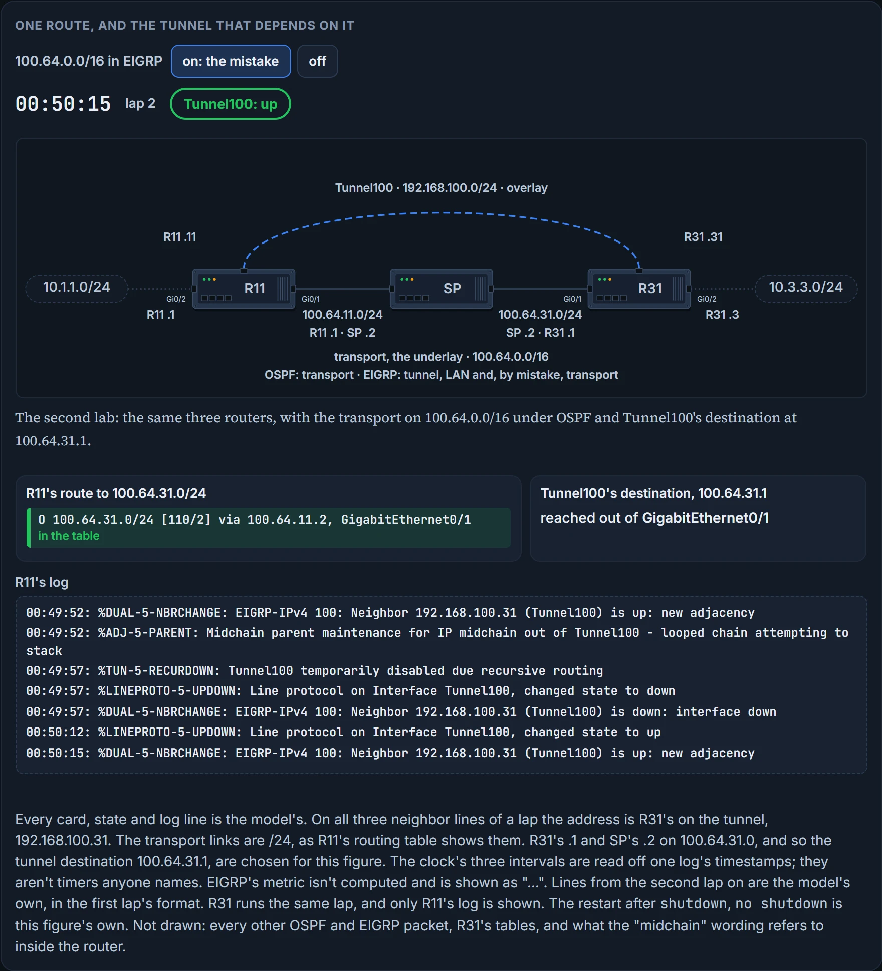
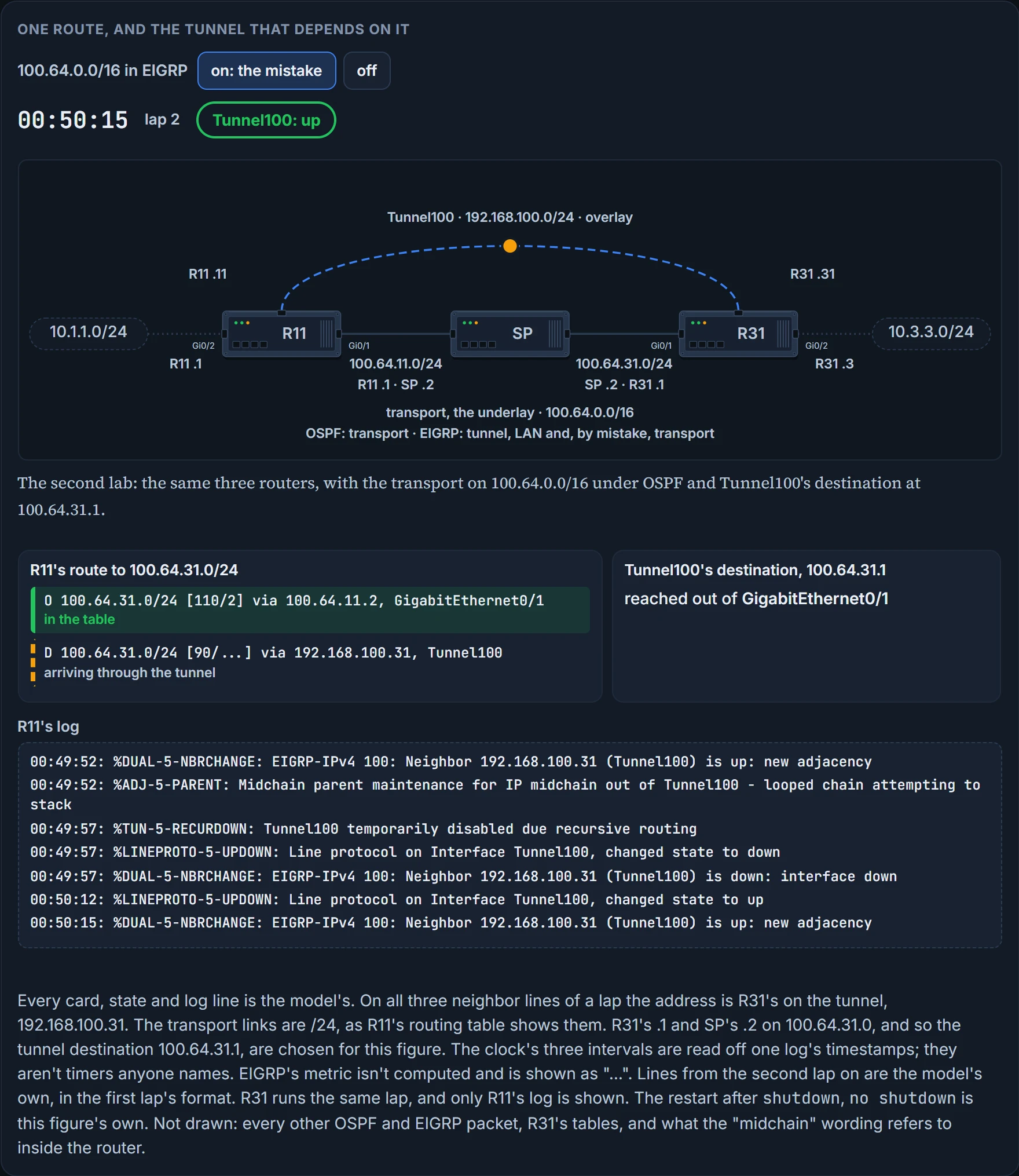
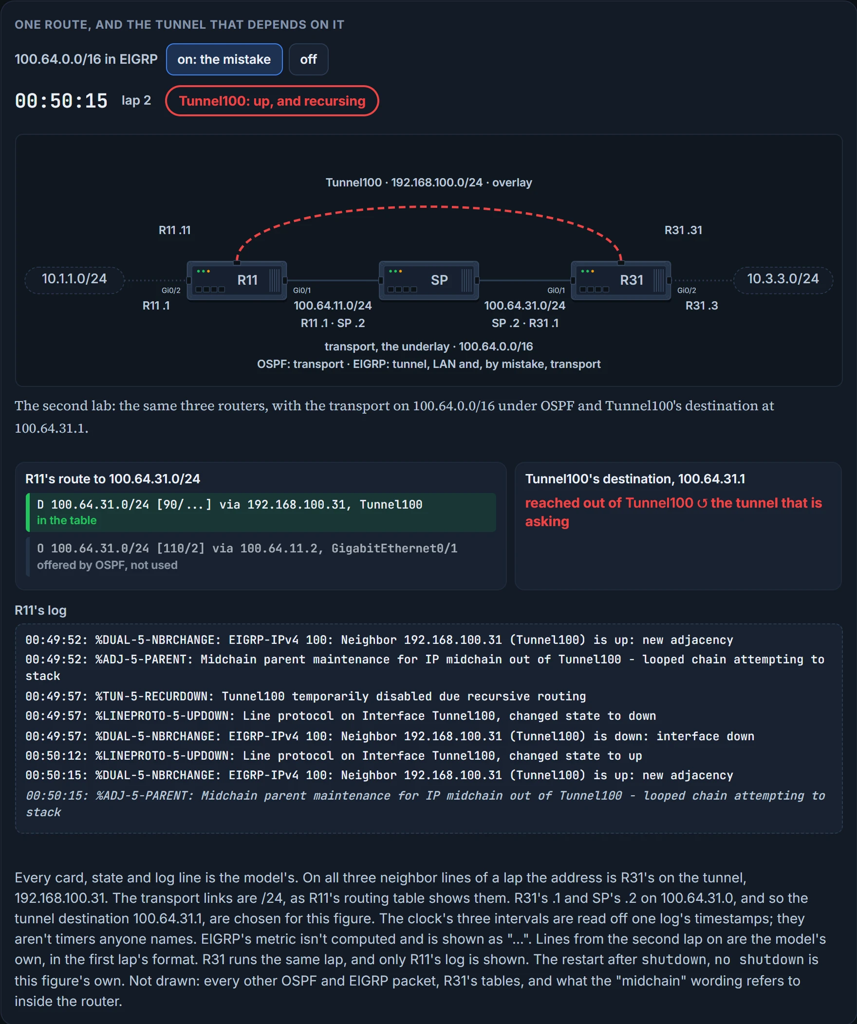
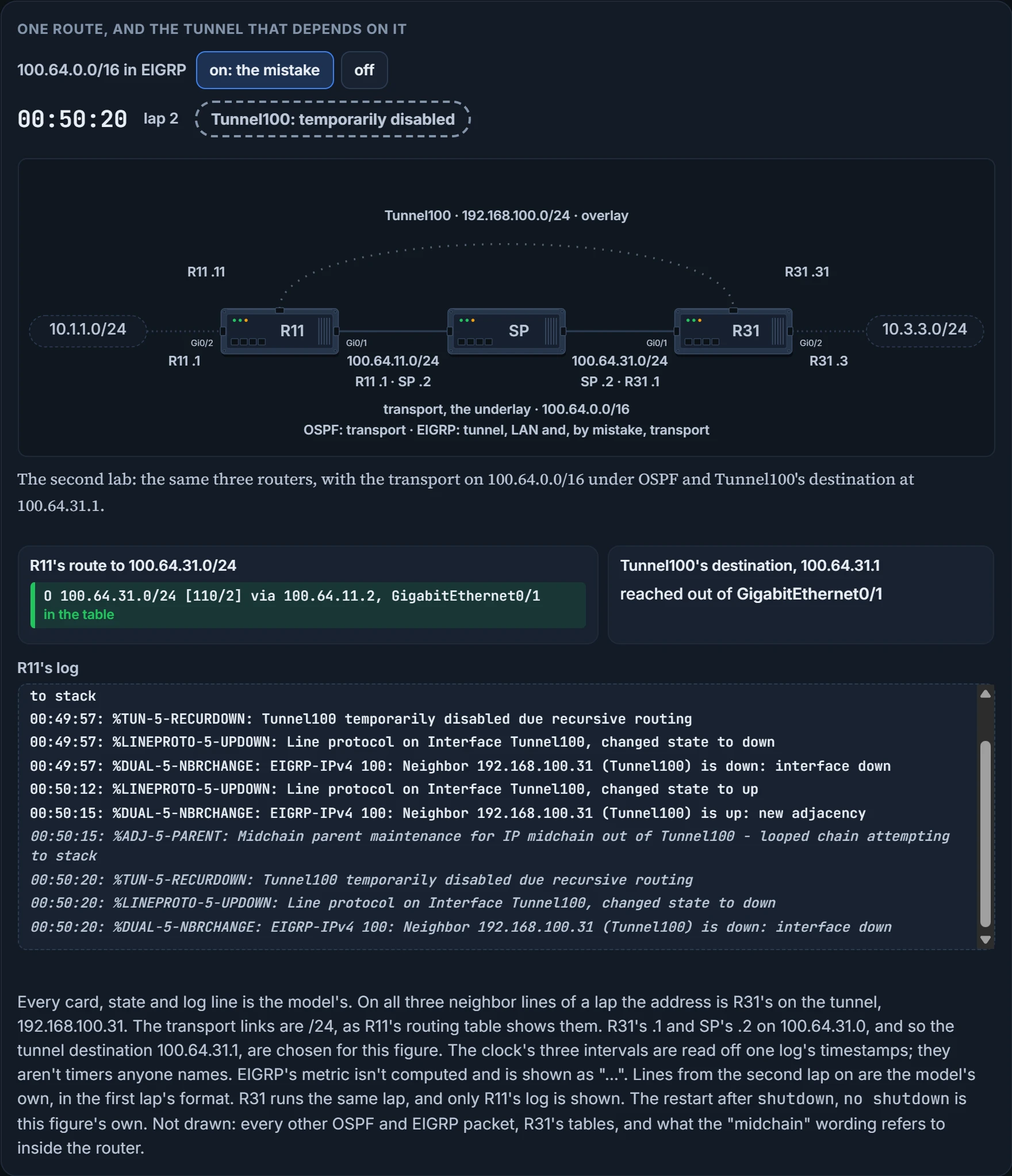
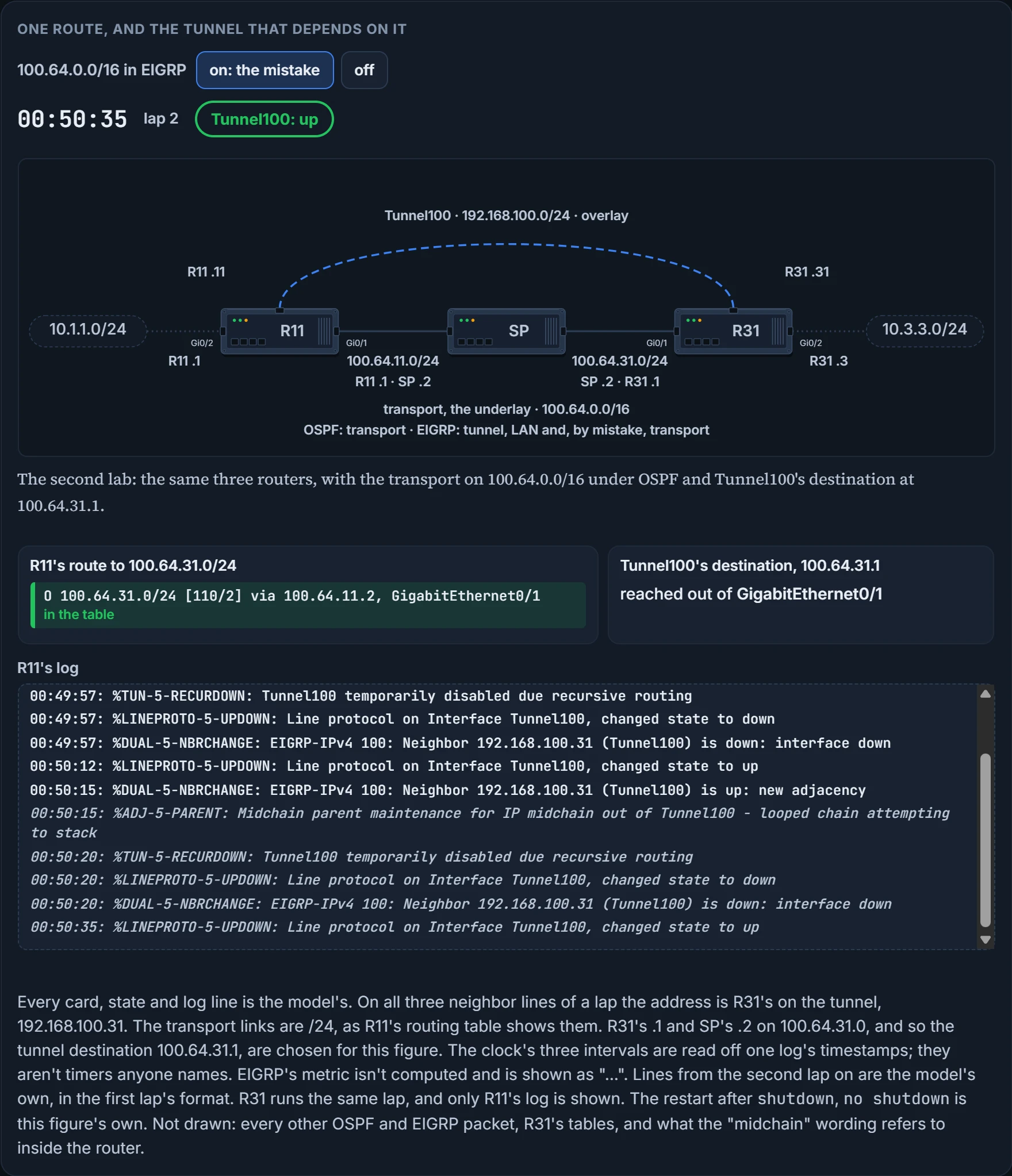
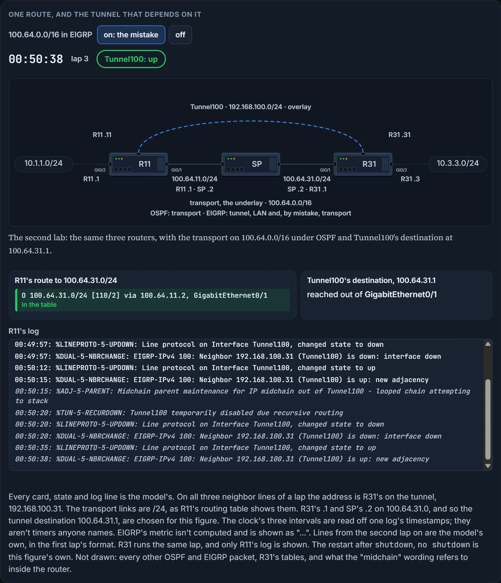
EIGRP's goes in, at 90 against 110, and its next hop is 192.168.100.31, out of Tunnel100. So the route to the tunnel's destination now points into the tunnel. To send a GRE packet to 100.64.31.1, R11 would have to put it in a GRE packet to 100.64.31.1.
Now ask the last section's rule what it makes of that, and notice it has no complaint. A route to the tunnel destination exists, so by that rule the line protocol may stay up. The two rules you brought into this section explain how the tunnel got here. Neither says what happens next. That takes a third rule, and it comes in two parts.
First, the condition has a name. The routers then try to use the tunnel to reach the tunnel endpoint address, which is not possible, and this scenario is known as recursive routing. It's the mailroom looking up the other building's address in a letter that's inside the envelope it's trying to address. The definition to carry into the exam: recursive routing is a routing loop for encapsulated interfaces in which the router's preferred path is to take the tunnel rather than the underlay network, which then brings down the tunnel interface.
Continue the lesson
The whole lesson, with its drawings and its questions. The rest of this section and 2 more after it.