
Routing over DMVPN, front-door VRF and failure detection
Over a hub-and-spoke tunnel, routing protocols need adjusting. EIGRP's split horizon stops the hub sending one spoke's routes to another, and next-hop-self hides the real next hop; OSPF needs a network type that suits the shape; BGP, which hears nobody it was not told about, uses dynamic neighbours on the hub. A front-door VRF gives the transport its own routing table.
By Arif, founder of Daveth · Updated
The full 18 min walkthrough is in Daveth Pro (Network). See what the plan opens
What this page answers
How do you run EIGRP over DMVPN?
Disable split horizon on the hub's tunnel, no ip split-horizon eigrp or no split-horizon in named mode, so spokes learn each other's routes; for spoke-to-spoke paths, also no ip next-hop-self eigrp, so the real next hop is kept. Read it in “Who hears whom: EIGRP”
How do you run OSPF over DMVPN?
Pick a network type that suits a hub and spokes. With broadcast, the hub must be the DR, because the DR has to be reachable in a single hop and the spokes cannot hear each other. With point-to-multipoint, each router's address is advertised as a /32 host route, which you must block. Read it in “Who hears whom: OSPF”
Three lines nobody explained
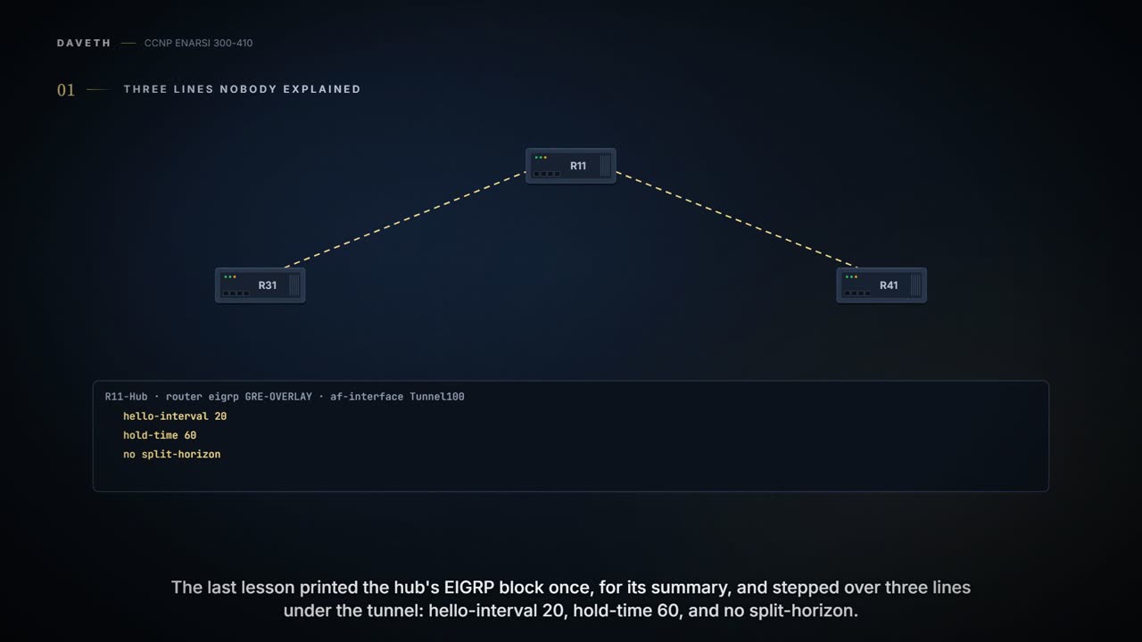
The last lesson printed the hub's EIGRP block once, for its summary line, and stepped over the rest. Here are the lines it stepped over, with the summary line and the block's closing lines trimmed:
R11-Hub
router eigrp GRE-OVERLAY
 address-family ipv4 unicast autonomous-system 100
  af-interface Tunnel100
   hello-interval 20
   hold-time 60
   no split-horizon
Three settings under one interface, and you wouldn't type any of them on an Ethernet port.
Why are they right here? Because of what Tunnel100 is: a multipoint interface, a single mGRE tunnel interface, provides connectivity to multiple routers in the same subnet out the single interface, as does Ethernet. A routing protocol sees there what it sees on a LAN, and applies its LAN rules until you tell it otherwise.
It isn't one. On this subnet R31's packets go to R11 and nowhere else, unless a shortcut happens to exist. Everyone can reach the hub. Nobody else is promised anything.
That's one thing a cable would have settled for you, and there are two more. A cable has an obvious way out: the port. A tunnel's way out is a route lookup. And a cable has a far end whose death takes the port down with it. A multipoint tunnel has many far ends, and its interface doesn't go down for any of them.
So this lesson asks one hub three questions. Who hears whom? Which way is out? Is anyone there? Each has a default answer that suits a wire and not a tunnel, and each time the fix is a line or two that you can read back afterwards.
Who hears whom: EIGRP
Start with the line you've met. Split horizon: a route learned inbound on an interface isn't advertised out the same interface. EIGRP has the rule on for every interface by default, and where an interface connects to a multi-access medium that doesn't give full-mesh connectivity it needs to be disabled. A DMVPN hub's tunnel is that medium. Picture three routers: R1 the hub, R2 and R3 spokes that can only communicate with the hub, and each spoke's table holding exactly one remote route, R1's 10.1.1.0/24. Expect it as an exam question, in more than one wording: spokes that aren't learning each other's routes, and the answer each time is split horizon left enabled on the hub's mGRE interface.
The cure, in both configuration styles:
R1 (Classic Configuration)
interface tunnel 100
 ip address 10.123.1.1 255.255.255.0
 no ip split-horizon eigrp 100
R1 (Named Mode Configuration)
router eigrp EIGRP-NAMED
address-family ipv4 unicast autonomous-system 100
 af-interface tunnel 100
  no split-horizon
Verify it where EIGRP keeps it: show ip interface goes on saying split horizon is enabled, and show ip eigrp interfaces detail tunnel 0 is where the line "Split-horizon is disabled" prints. The first proves nothing about EIGRP. The second proves the hub may advertise a route back out of the tunnel it arrived on; it doesn't prove any spoke received one, or what next hop it holds.
IPv6 is no different: split horizon is an issue in EIGRP for IPv6 designs too, a DMVPN's multipoint hub is the usual case, and it needs to be disabled on the hub's interface so routes learned from the spokes can be advertised back out to the other spokes. In named mode that's the same no split-horizon, under the IPv6 address family's af-interface.
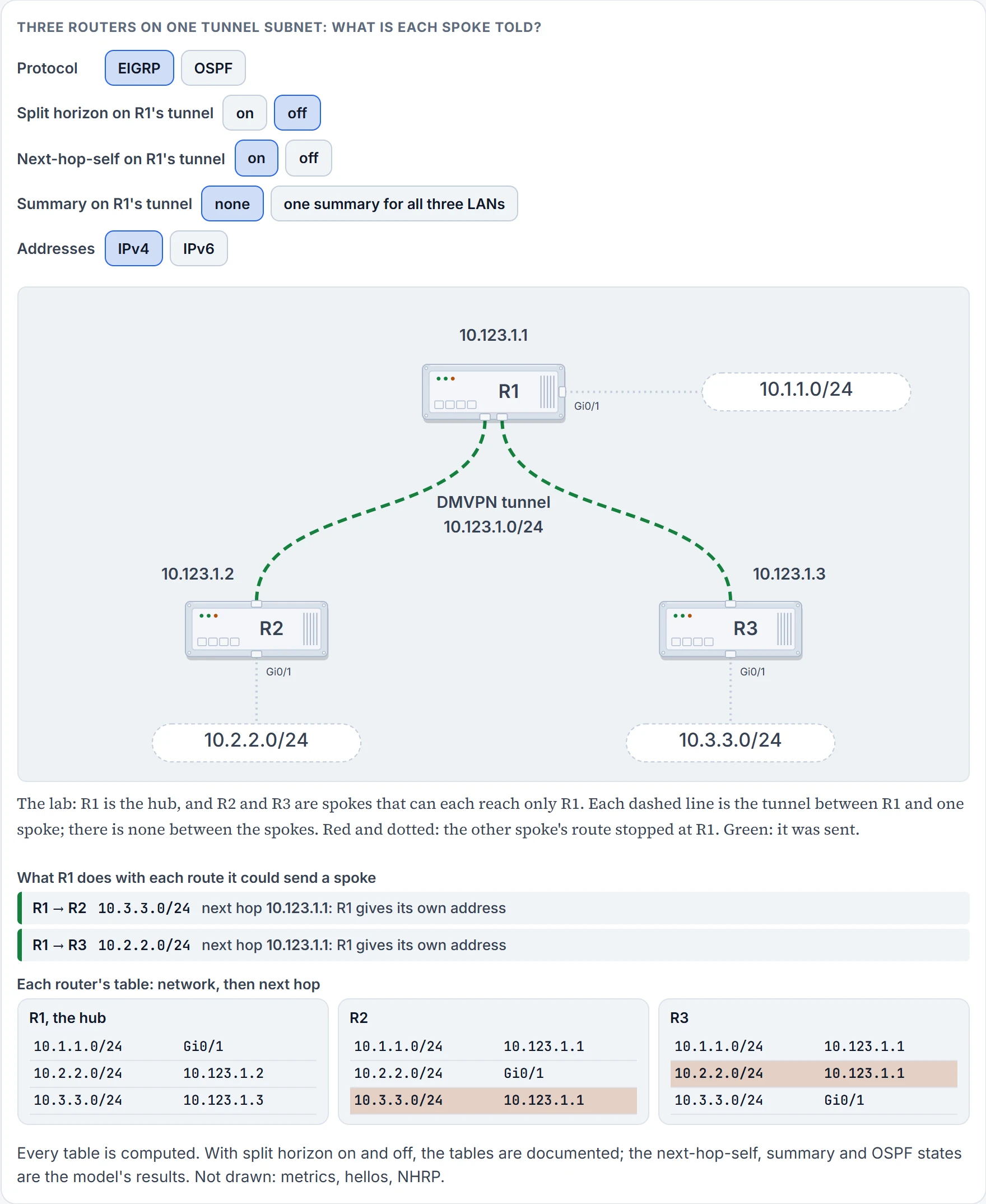
It's 10.123.1.1, the hub: R2's new line reads 10.3.3.0/24 by way of 10.123.1.1. R2 heard about that LAN from R1, and R1 gave its own address as the way there.
In Phase 1 that's what you want: the only tunnel R2 has goes to the hub, so the hub had better be the next hop.
Turn it round. Suppose you wanted R2 to hold R3's own tunnel address as the next hop, 10.123.1.3. EIGRP can do that, with a second line on the hub's tunnel. Here is the pair from a documented hub sample, each under its own comment:
! Turns off split horizon on the mGRE tunnel interface; otherwise, EIGRP will not advertise routes that are learned via the mGRE interface back out that interface.
no ip split-horizon eigrp 1
! Enables dynamic, direct spoke-to-spoke tunnels when using EIGRP.
no ip next-hop-self eigrp 1
Two lines, two different jobs. The first decides whether a spoke hears about another spoke's LAN at all. The second decides whose address it's told to send to. A documented sample of show ip eigrp interfaces detail, taken with the second line typed, has a line that begins "Next-hop-self disabled, next-hop info forwarded".
Do you need that second line? In Phase 3 each spoke's route points at the hub, the first packet goes to the hub, and NHRP then installs something better. The Phase 3 hub at the top of this page has no next-hop line at all. The working rule: the next-hop line belongs to the older design, Phase 2, where the routing protocol had to hand each spoke the far spoke's address. In Phase 3 the routing protocol only has to get the packet to the hub.
One oddity about that hub. It has a summary and no split-horizon together, and a summary is the hub's own route. It wasn't learned on the tunnel, so split horizon has no reason to hold it back. Don't lean on that: a hub whose summary is ever removed needs no split-horizon the same minute.
The other two lines, hello-interval 20 and hold-time 60: how often the hub says hello on this interface, and how long its neighbors wait before giving up on it. A hub with hundreds of spokes has hundreds of hellos to send every interval, so the interval is stretched. Hold that sixty: the section on failure comes back to it.
One more interface line touches EIGRP: the tunnel's bandwidth. Its default is 9 kilobits per second, and setting it to at least 1000 is critical if EIGRP is used over the tunnel interface. Bandwidth is in the metric, and EIGRP paces its own packets against it.
We haven't confirmed on a router, for this section: the named-mode form of the next-hop line, and what a router prints for it; that a summary reaches the spokes with split horizon still on, which is the model's result; the reason for 20 and 60, which is ours; and the IPv6 form of no split-horizon, taken from the IPv4 one.
Who hears whom: OSPF
Same tunnel, different protocol, same question. OSPF's version of "everyone hears everyone" is the designated router, the DR: on a multi-access segment every router hands its news to the DR and takes everyone else's from it.
On Ethernet it doesn't matter who the DR is. Over a hub-and-spoke network such as Frame Relay, or with a DMVPN, it does matter, because the underlying Layer 2 topology does not line up with the Layer 3 addressing. The DR has to be reachable in a single hop, hellos aren't relayed by other routers, and so on three routers shaped like the figure above the DR must be R1, the hub. If a spoke wins the election, the other spokes can't form an adjacency with it and routes go missing. The cure is the one the OSPF lessons gave for any hub and spokes: priority 0 on the spokes.
What DMVPN adds is a choice, and it comes from the same question as EIGRP's: what next hop does a spoke end up holding? In Phase 3, because the spokes can use routes with the IP next hop set to the hub router, and not the remote spoke router as before, you can configure OSPF to use point-multipoint network mode rather than broadcast network mode; and doing so removes the DR and BDR requirements. Read it backwards and you have the older design too: broadcast mode, the hub as DR, and each spoke's route pointing at the remote spoke itself. The figure's protocol switch draws both.
Point-to-multipoint has a price: when using OSPF point-to-multipoint, you must block the OSPF /32 routes. A point-to-multipoint interface advertises each router's own address as a host route, and the cure is a prefix list applied with distribute-list ... out on all hub and spoke routers.
One thing OSPF can't give you here at all: the hub's summary. With OSPF each spoke still has all individual routes, because the DMVPN network must be in a single OSPF area but you cannot summarize routes within an OSPF area.
Set the network type on purpose, the same on every router of the cloud.
We haven't confirmed on a router, for this section: what network type a tunnel interface takes when you set none, and the exact lines of the /32 filter.
Who hears whom: BGP
BGP's version of the question is blunter, because BGP hears nobody it wasn't told about. It doesn't use hellos to find neighbors, and two BGP neighbors cannot discover each other dynamically. Every session is two neighbor lines, one on each router.
Put that on a DMVPN hub. A hundred branches is a hundred neighbor lines on the hub, and branch 101 means logging in to the hub: the chore the design was meant to end. DMVPN's promise is that the size of the configuration on the hub router remains constant even if spoke routers are added to the network. NHRP keeps that promise for the tunnel, and an IGP for routing. BGP, as you learned it, breaks it.
The exam topic is called "Dynamic neighbor", and for BGP's half of it there is one sentence to carry. True or false: BGP supports dynamic neighbor discovery by both routers. False. BGP neighbors are statically defined; there is a feature that supports dynamic discovery by one peer, but the other router must still statically configure the remote BGP peer.
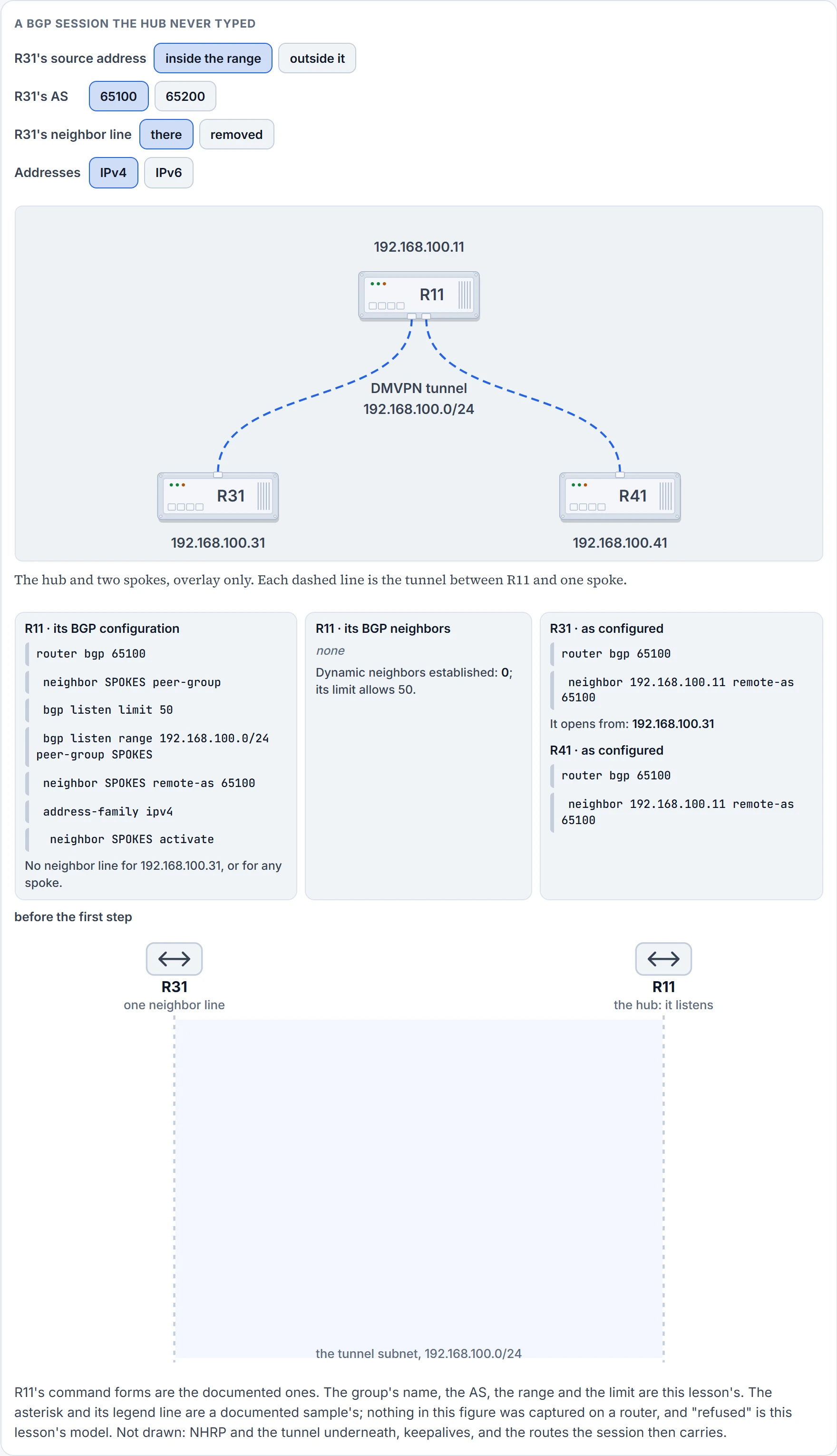
Step 1 of 7 Nothing has been sent. R11's neighbor table is empty, and its configuration names no spoke.
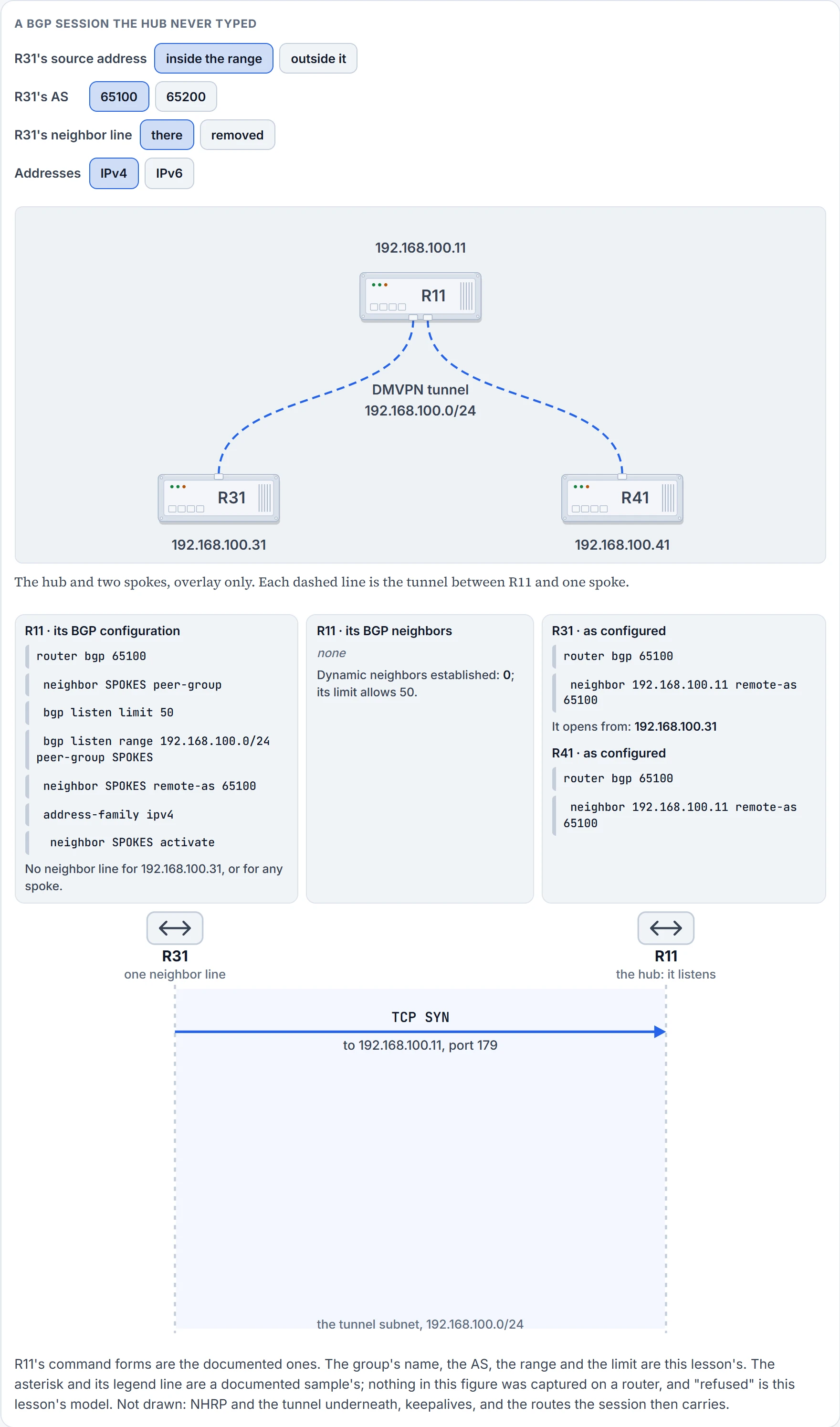
Step 2 of 7 R31 has a neighbor line, so it has an address to open to. It sends a TCP SYN to 192.168.100.11, port 179: a session starts with one router opening a TCP connection to the other.
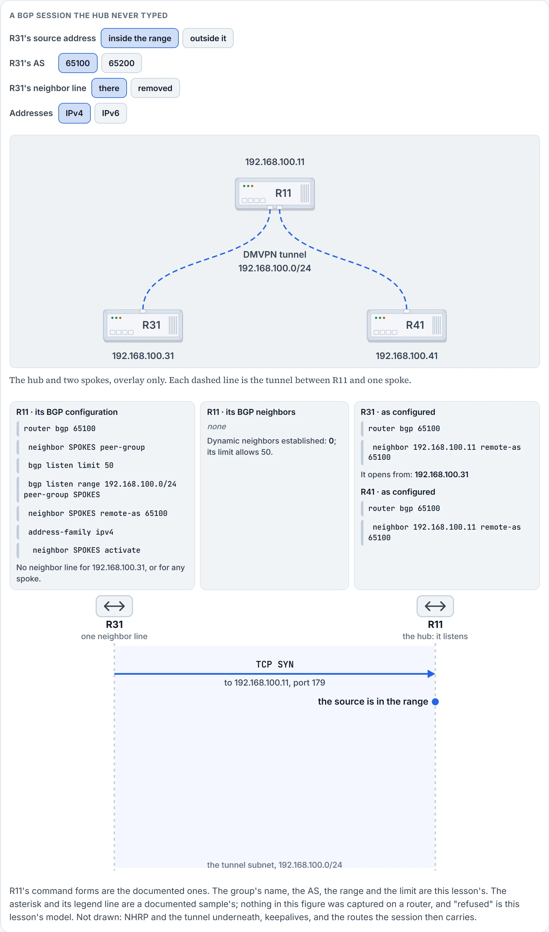
Step 3 of 7 R11 has no neighbor line for 192.168.100.31. It does have a listen range that holds it, 192.168.100.0/24, and it has made fewer dynamic neighbors than its limit of 50 allows.
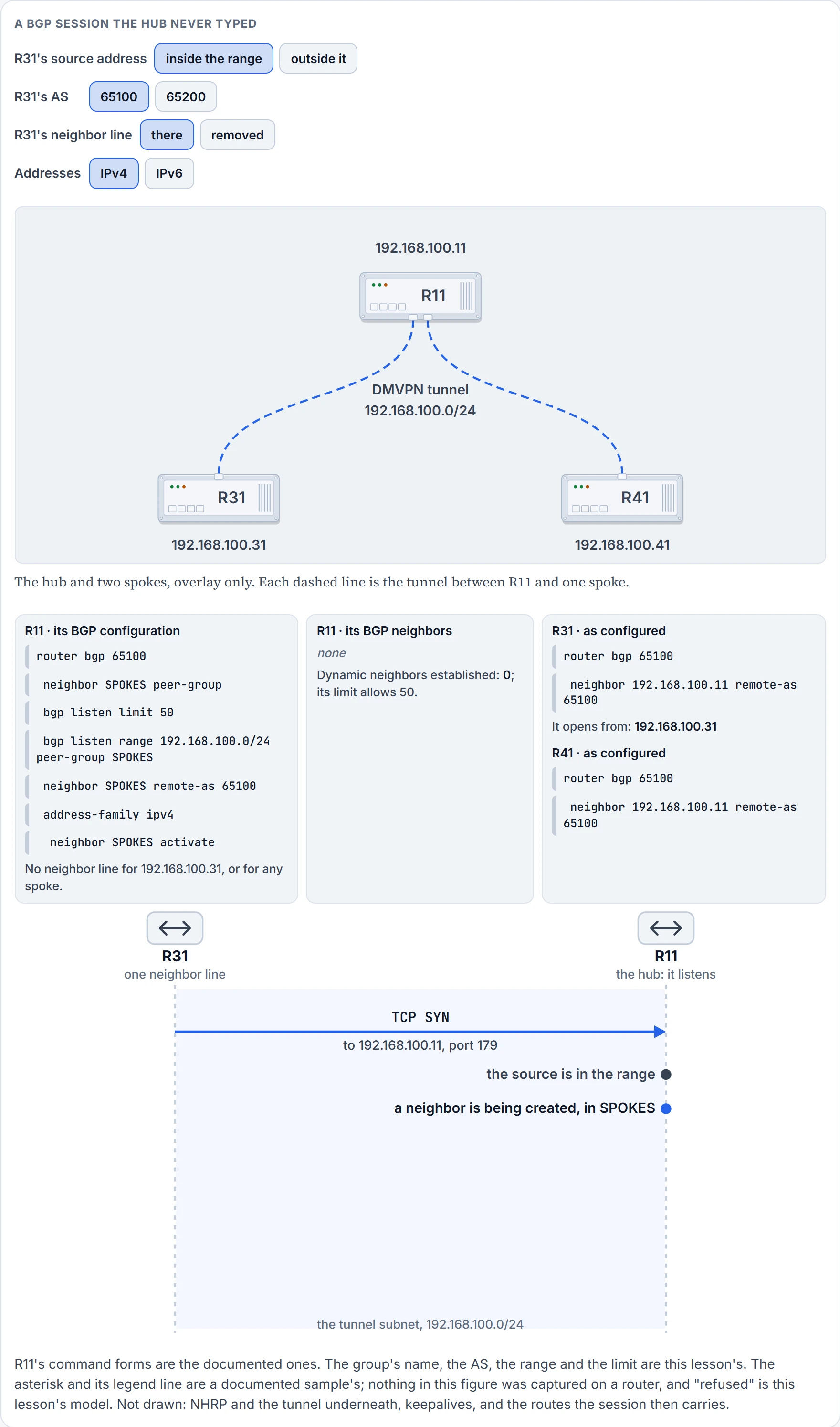
Step 4 of 7 The connection triggers R11 to create a neighbor for 192.168.100.31 as a member of SPOKES. The new neighbor inherits the group's configuration: remote AS 65100. It isn't in R11's table yet: nothing is established.
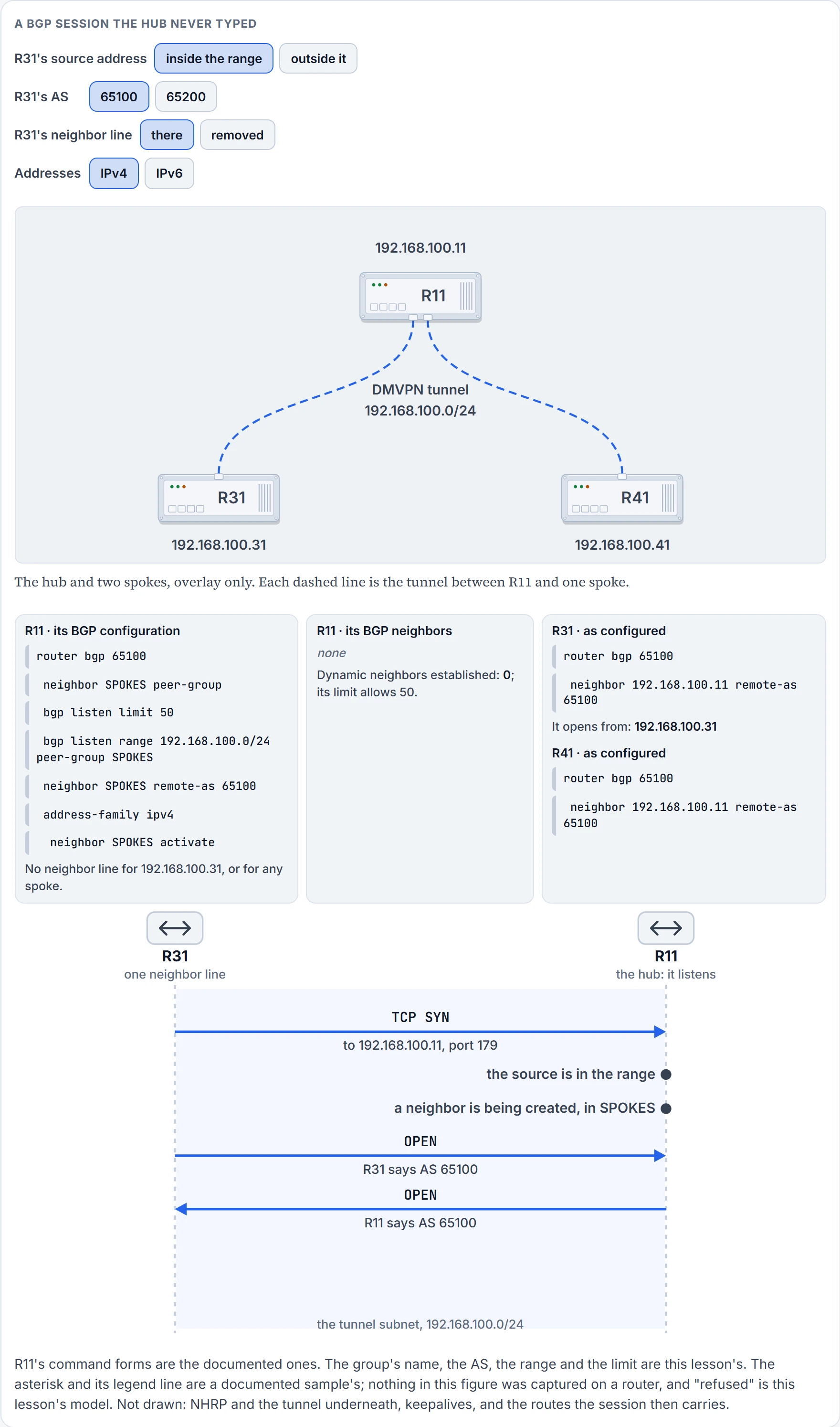
Step 5 of 7 The two exchange OPEN messages. R31 says AS 65100, which is the group's remote AS.
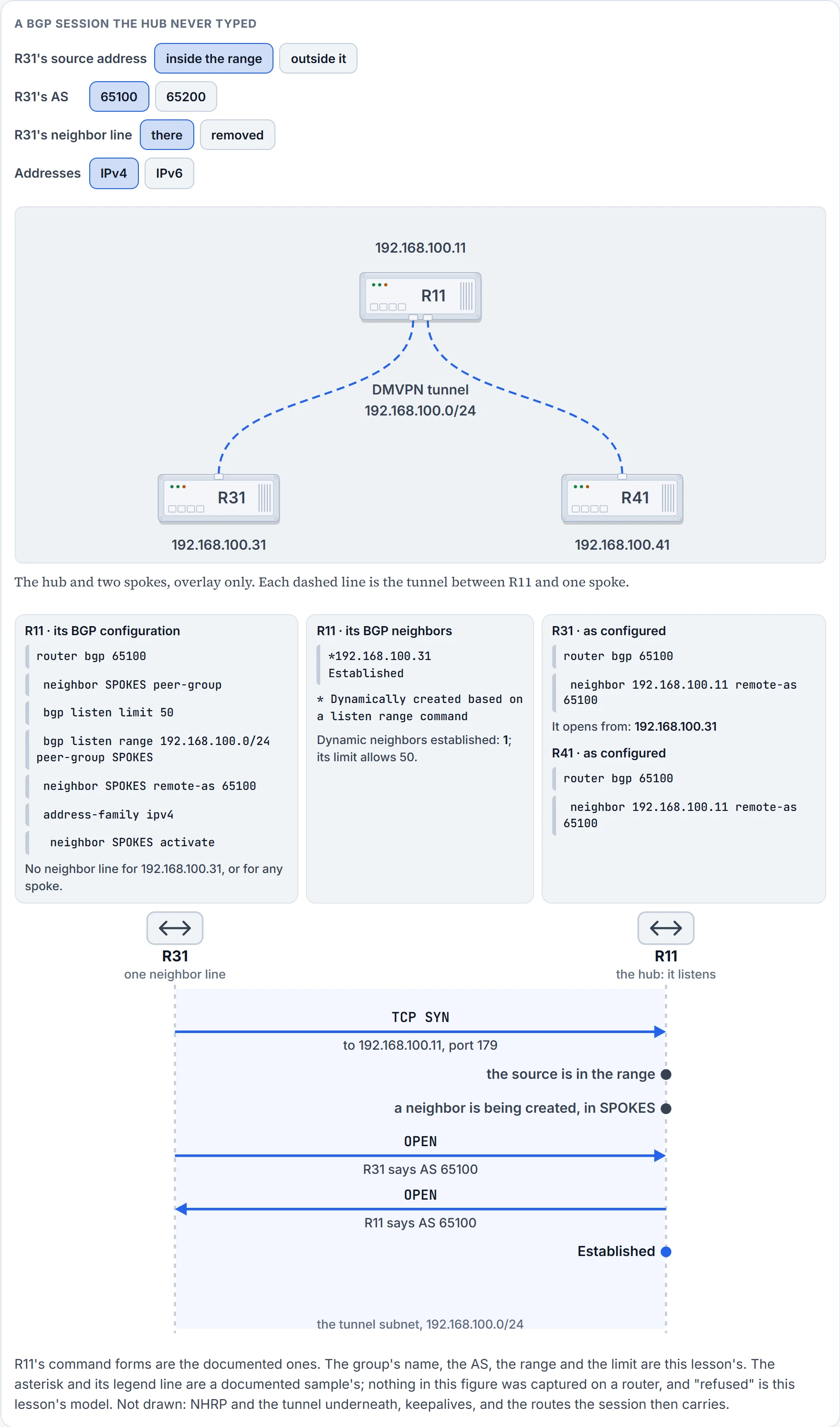
Step 6 of 7 Established. R11's table gains 192.168.100.31 with an asterisk in front, and the legend line under the table says what the asterisk means.
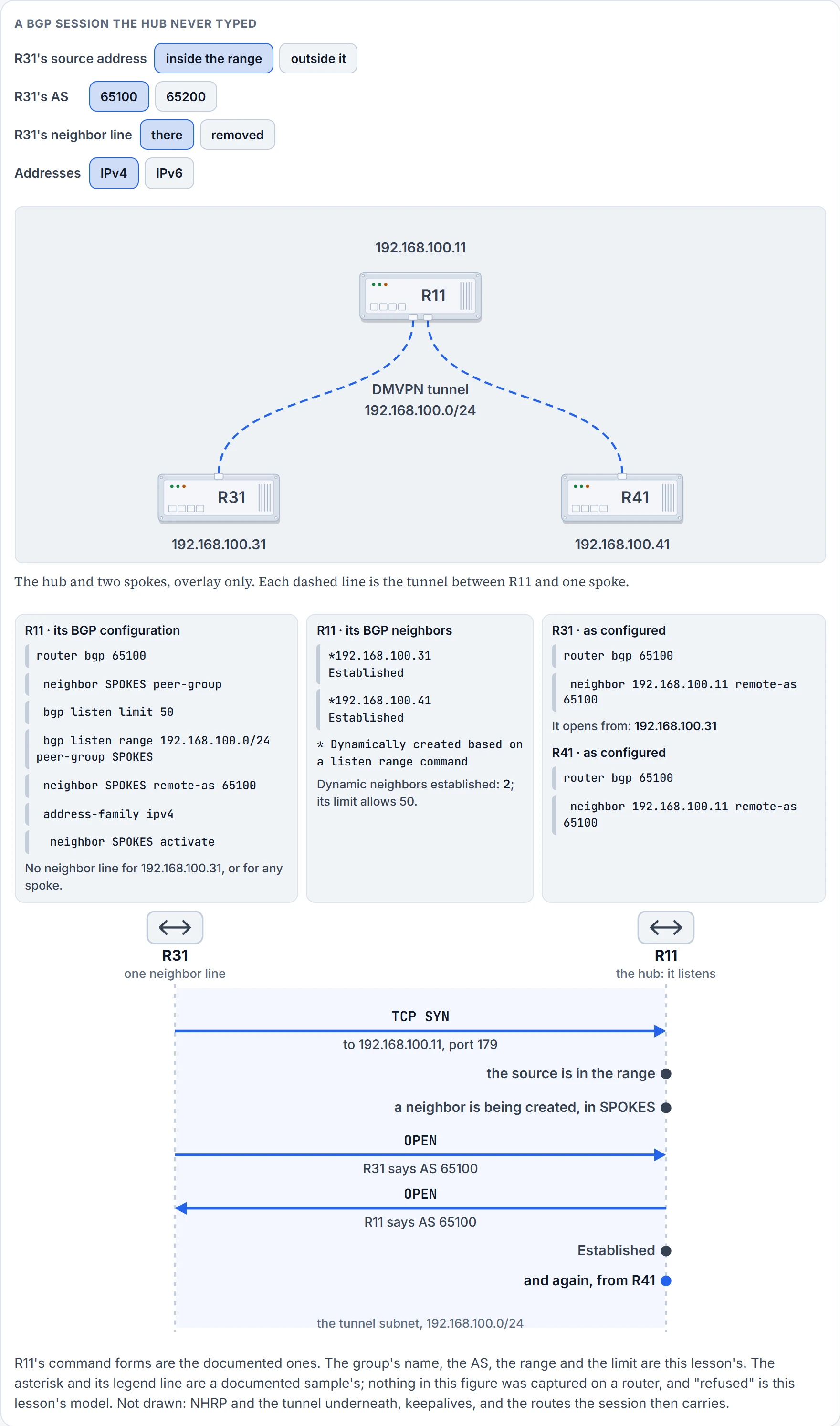
Step 7 of 7 R41 does the same five steps from 192.168.100.41. Two neighbors, and R11's configuration card hasn't changed by a character.
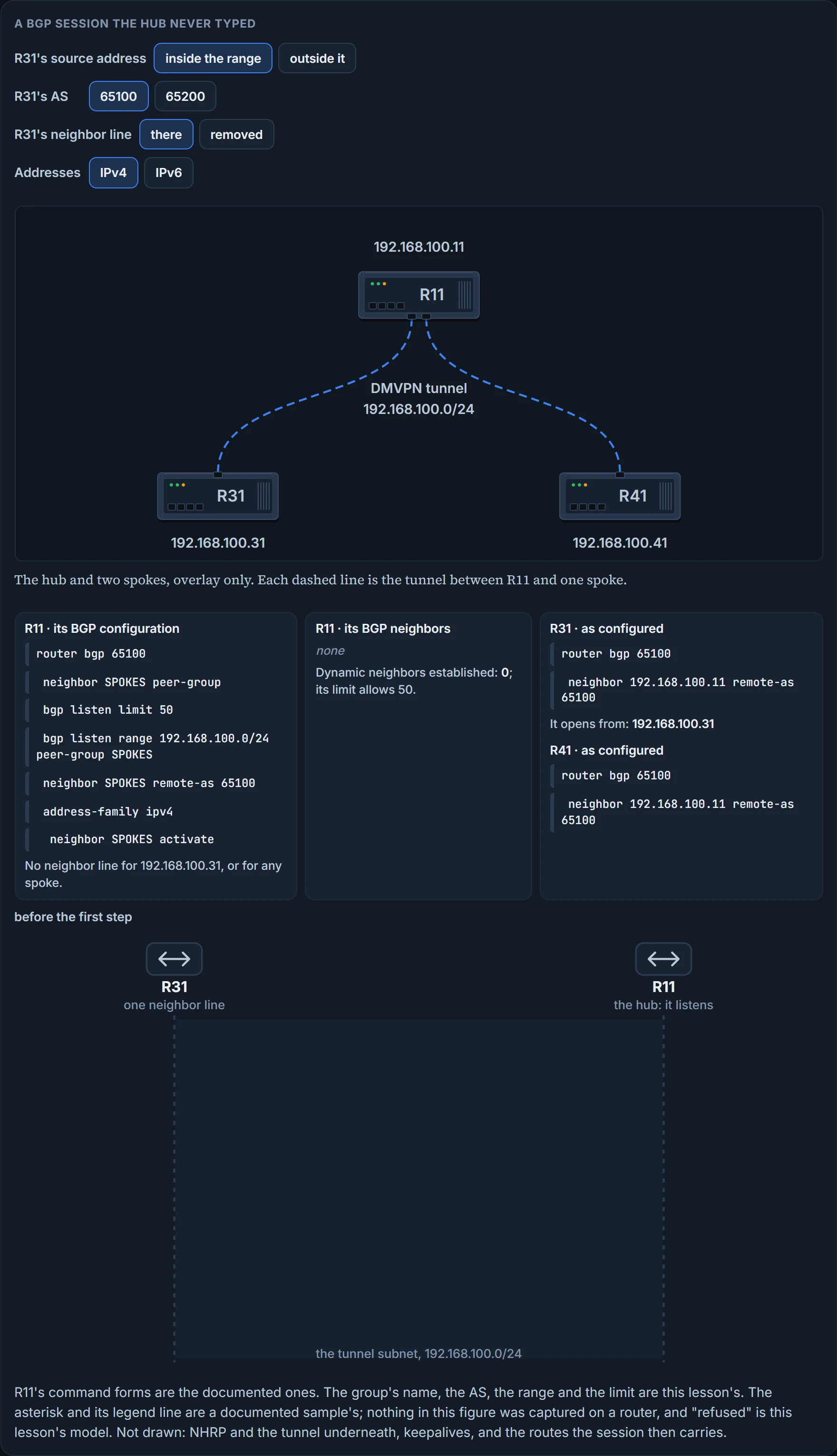
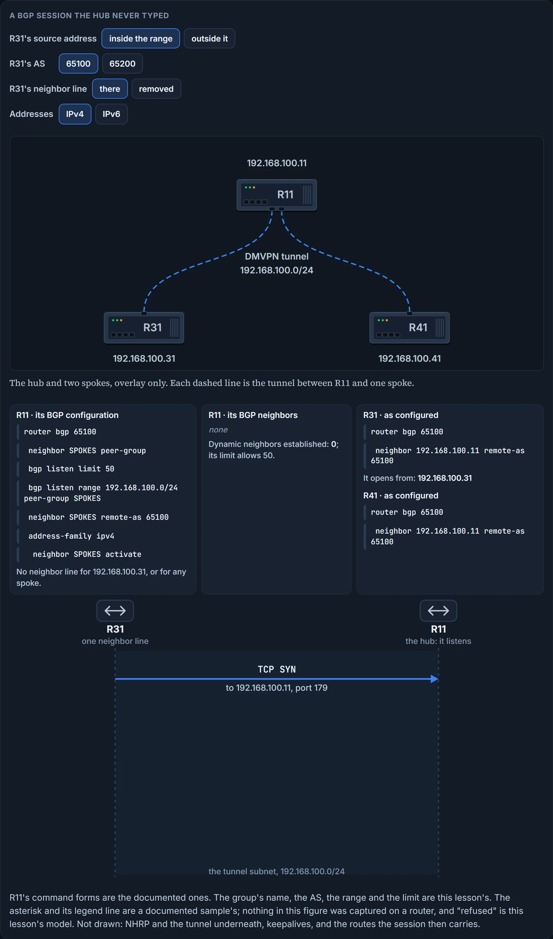
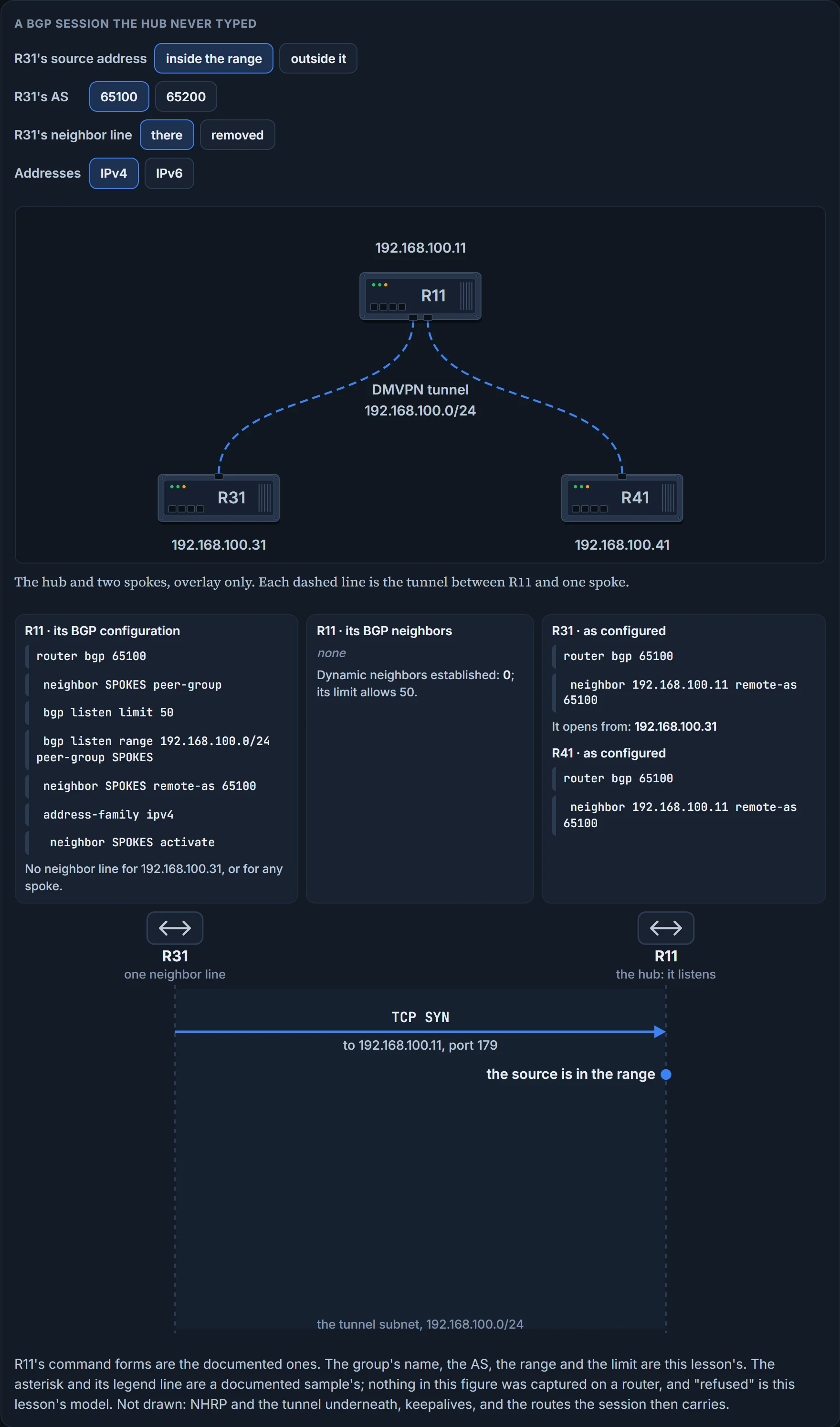
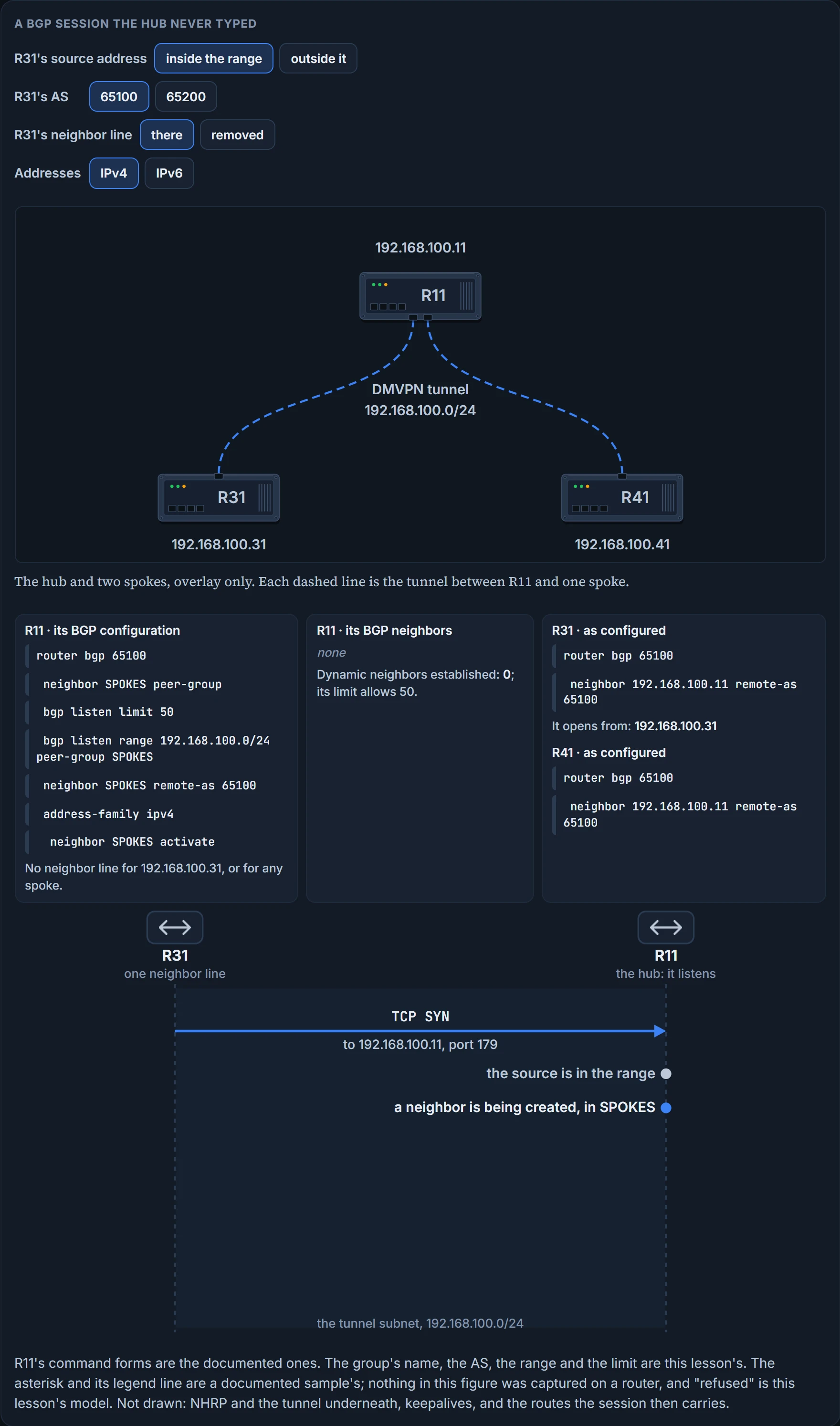
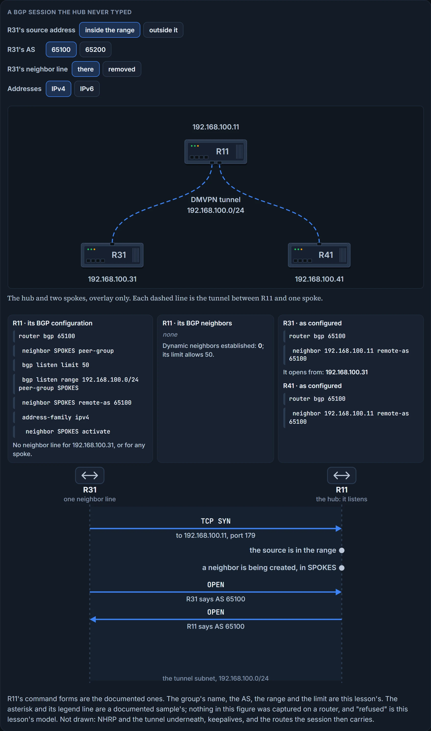
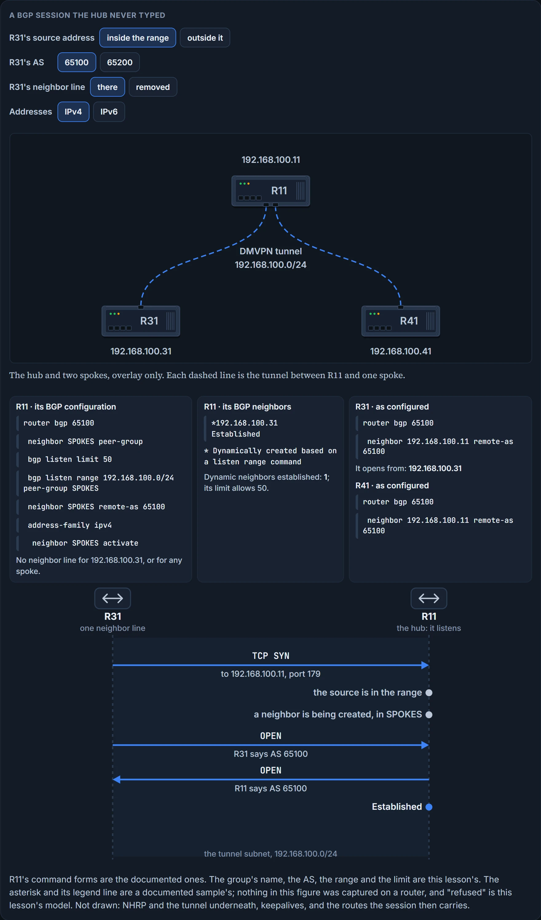
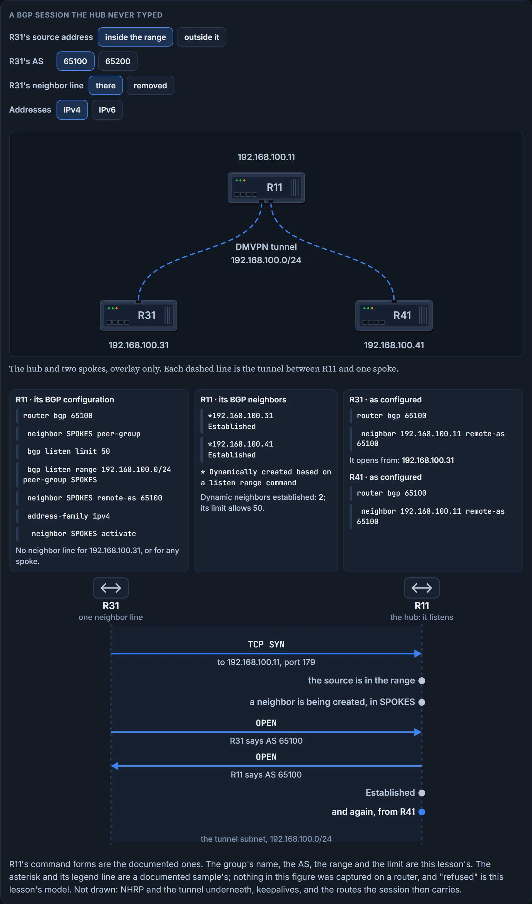
R31 sends it. It's the only one that can. R31 has R11's address; R11 has nobody's. So the hub's whole part is to listen, and the feature is a rule for what it does when a connection arrives from an address it has no line for.
The feature is called BGP dynamic neighbors, and its rule has three parts. After a subnet range is configured for a BGP peer group and a TCP session is initiated by another router for an IP address in the subnet range, a new BGP neighbor is dynamically created as a member of that group. A dynamic BGP neighbor will inherit any configuration for the peer group: the remote AS, the policy, the timers. And once the range and the group are in, dynamic BGP neighbor creation does not require any further CLI configuration on the initial router. One range, one group, however many spokes. On a DMVPN hub the natural range is the tunnel's own subnet.
The lines, in the order the documented task types them, with this lab's addresses:
router bgp 65100
 neighbor SPOKES peer-group
 bgp listen limit 50
 bgp listen range 192.168.100.0/24 peer-group SPOKES
 neighbor SPOKES remote-as 65100
 address-family ipv4
  neighbor SPOKES activate
The group and its remote AS you've typed before. The two bgp listen lines are new, and both sit directly under router bgp. The range line ties a prefix to the group. The limit line caps how many dynamic neighbors the router will create, and it has a default: the default number of BGP dynamic neighbors is set to 100 if no max limit is configured on the router. A listen range makes a neighbor of whoever opens a session from inside it, so the advice is to keep the listen limit and listen range the same as the planned neighbor count, in order to prevent unexpected peers.
A third router-level line exists for the day a typed neighbor has to sit inside a listen range: bgp listen block with its address, to exclude a neighbor if you require a static peer in the listen range. The range can then hold both static and dynamic peers.
Then the last two lines, the ones that look out of place: the group is activated by name under the address family. Usually BGP peer groups cannot be activated using this command, but the listen range peer groups are a special case.
IPv6 doesn't move the range line. A documented IPv6 sample has bgp listen range 2001::0/64 peer-group group192 directly under router bgp 100, not inside an address family, and then activates the group under the IPv6 unicast address family. On this lab's addresses that is a second range line beside the first, bgp listen range 2001:DB8:192:168:100::/80 peer-group SPOKES, and neighbor SPOKES activate under address-family ipv6.
How do you tell, on the hub, a neighbor nobody typed? The summary marks it. This is a documented sample from another network, a router with a limit of 200:
Router# show ip bgp summary
BGP router identifier 192.168.3.1, local AS number 64503
BGP table version is 1, main routing table version 1
Neighbor        V    AS MsgRcvd MsgSent   TblVer  InQ OutQ Up/Down  State/PfxRcd
*192.168.3.2    4 64502       2       2        0    0    0 00:00:37        0
* Dynamically created based on a listen range command
Dynamically created neighbors: 1/(200 max), Subnet ranges: 1
BGP peergroup group192 listen range group members:
192.168.0.0/16
The asterisk in front of the address, and the legend line under the table that says what the asterisk means. The count on the next line is neighbors created against the limit. What it proves: the hub made that neighbor from a listen range when the far end opened a session. What it doesn't: that the session carries any route.
The question this section owes you: what next hop does a spoke hold for another spoke's LAN? With every router in one AS, none at first, and the tunnel isn't why. A route learned from one internal neighbor isn't passed to another unless the hub reflects it, which is the route-reflector lesson's subject. When it does reflect, BGP's answer is the opposite of EIGRP's. iBGP peers do not modify the next-hop address if the route has a next-hop address other than 0.0.0.0, and behind a reflector the next-hop address changes once, when the route is installed in the table of the first router to receive it, and remains the same on every router after it. On the overlay, that leaves each spoke holding the far spoke's own tunnel address, where EIGRP left it holding the hub's.
We haven't confirmed on a router, for this section: what a connection from outside the range, or from the wrong AS, is told (the figure's "refused" is this lesson's model); whether a session comes up before the group is activated; whether a /80 is accepted as an IPv6 range; what a hub lists once a dynamic neighbor's session has dropped; and that a reflecting hub leaves the far spoke's tunnel address as the next hop, which is this lesson's reading: those two rules applied to this tunnel.
Which way is out
Second question. The tunnel has to send its own packets, the GRE ones, to the far end's transport address. Through which interface?
Take R31 with two providers and a tunnel over each, which is how a branch typically gets resiliency: multiple transports, one DMVPN tunnel per transport. The question is how R31 would know which interface to use to send packets for tunnel 100, and how that changes for tunnel 200. If the router picks the correct interface, the tunnel comes up; if it picks the wrong interface, the tunnel never comes up. Here is what R31 has to decide with:
R31-Spoke# show ip route
! Output omitted for brevity
Gateway of last resort is 172.16.31.2 to network 0.0.0.0
S*    0.0.0.0/0 [254/0] via 172.16.31.2
               [254/0] via 100.64.31.2
C      100.64.31.0/30 is directly connected, GigabitEthernet0/2
C      172.16.31.0/30 is directly connected, GigabitEthernet0/1
Two defaults at distance 254, one per provider, equal. Both tunnels' destinations match the same line, and that line has both exits. And this can be further exacerbated if the hub routers need to advertise a default route across the DMVPN tunnel: a third 0.0.0.0/0, arriving through the very tunnel whose packets the first two are meant to carry.
The answer is a table each, and the tool is the VRF. VRF contexts create unique logical routers on a physical router, so that router interfaces, routing tables and forwarding tables are completely isolated from other VRF instances. For this router, that means the routing table of one transport network is isolated from the routing table of the other transport network, and the routing table of the LAN interfaces is separate from those of all the transport networks.
DMVPN tunnels are VRF aware, in the sense that the tunnel source or destination can be associated to a different VRF instance from the DMVPN tunnel itself. A tunnel interface was always two things: the interface your LAN's packets are routed into, and the sender of GRE packets on the underlay. Those two can live in different tables. The interface that faces the transport network goes in a transport VRF, the DMVPN tunnel is associated with a different one, and the VRF associated with the transport network is known as a front door VRF, FVRF.
It has two results, one per problem. Using an FVRF for every DMVPN tunnel prevents route recursion, because the transport and overlay networks remain in separate routing tables. And using a unique FVRF for each transport, associated to the correlating tunnel, ensures that packets will always use the correct interface.
Five steps to build one, and only the last is new:
- Create the VRF with
vrf definition vrf-name. - Initialize the address family for the transport network with
address-family {ipv4 | ipv6}; it can be IPv4, IPv6 or both. - On the transport interface,
vrf forwarding vrf-name. - Configure the address:
ip address ip-address subnet-mask, oripv6 address ipv6-address/prefix-length. - Associate the FVRF with the DMVPN tunnel with the interface parameter command
tunnel vrf vrf-name, on the tunnel.
Step 4 comes after step 3 for a reason: if an IP address is already configured on the interface, when the VRF instance is linked to the interface, the IP address is removed from that interface. VRF instances are locally significant, but the naming should be consistent to simplify operations.
Step 5 is the new line: tunnel vrf vrf-name associates a front door VRF instance to a DMVPN tunnel interface. Notice what it isn't. It is not vrf forwarding typed on the tunnel. A tunnel can carry both commands, and different VRF names need to be selected for this to be effective. Which is which? The VRF associated with the tunnel vrf command is the same as the VRF associated with the physical interface over which the tunnel sends packets: outer IP packet routing. The VRF associated with the tunnel by the forwarding command is the VRF that the packets are to be forwarded in as they exit the tunnel: inner IP packet routing. Outer and inner. One command says where the envelope is routed, the other where the letter is.
On R31, twice over:
R31-Spoke(config)# vrf definition INET01
R31-Spoke(config-vrf)# address-family ipv4
R31-Spoke(config-vrf-af)# vrf definition INET02
R31-Spoke(config-vrf)# address-family ipv4
R31-Spoke(config-vrf-af)# interface GigabitEthernet0/1
R31-Spoke(config-if)# vrf forwarding INET01
% Interface GigabitEthernet0/1 IPv4 disabled and address(es) removed due to
    enabling VRF INET01
R31-Spoke(config-if)# ip address 172.16.31.1 255.255.255.252
R31-Spoke(config-if)# interface GigabitEthernet0/2
R31-Spoke(config-if)# vrf forwarding INET02
% Interface GigabitEthernet0/2 IPv4 disabled and address(es) removed due to
    enabling VRF INET02
R31-Spoke(config-if)# ip address dhcp
R31-Spoke(config-if)# interface tunnel 100
R31-Spoke(config-if)# tunnel vrf INET01
R31-Spoke(config-if)# interface tunnel 200
R31-Spoke(config-if)# tunnel vrf INET02
Each physical interface goes in, loses its address with a message, and gets it back, the second one from DHCP. Each tunnel gets one tunnel vrf line and no vrf forwarding line, so both tunnels' inner side stays where it was.
Each new table needs a way to the internet. FVRF interfaces that are assigned an IP address by DHCP automatically install a default route with an AD of 254, which is where the two defaults above came from. FVRF interfaces with static addressing require only a static default route in the FVRF context, ip route vrf vrf-name 0.0.0.0 0.0.0.0 next-hop-ip. GigabitEthernet0/1 is addressed by hand now, so INET01 gets that one line, and INET02 needs none because it gets its route from the DHCP server:
R31-Spoke
ip route vrf INET01 0.0.0.0 0.0.0.0 172.16.31.2
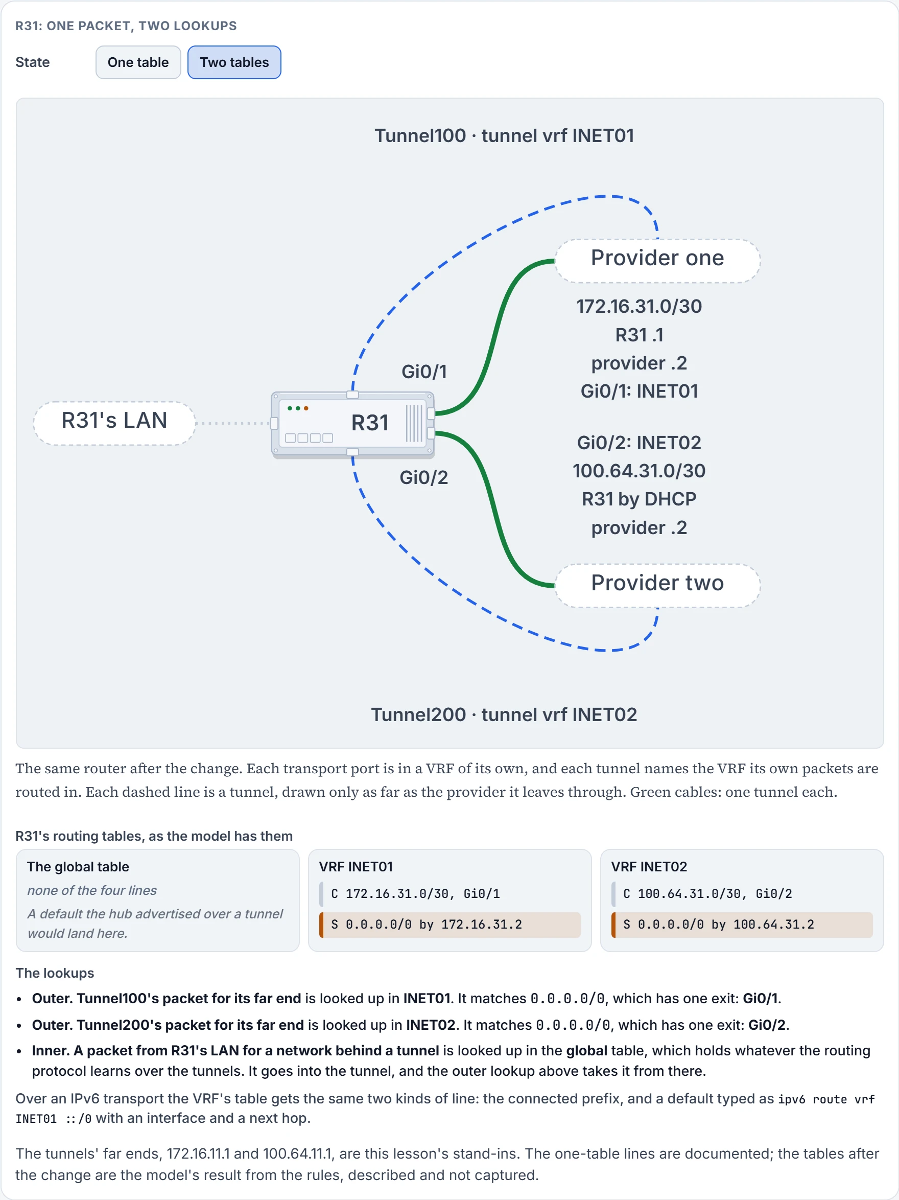
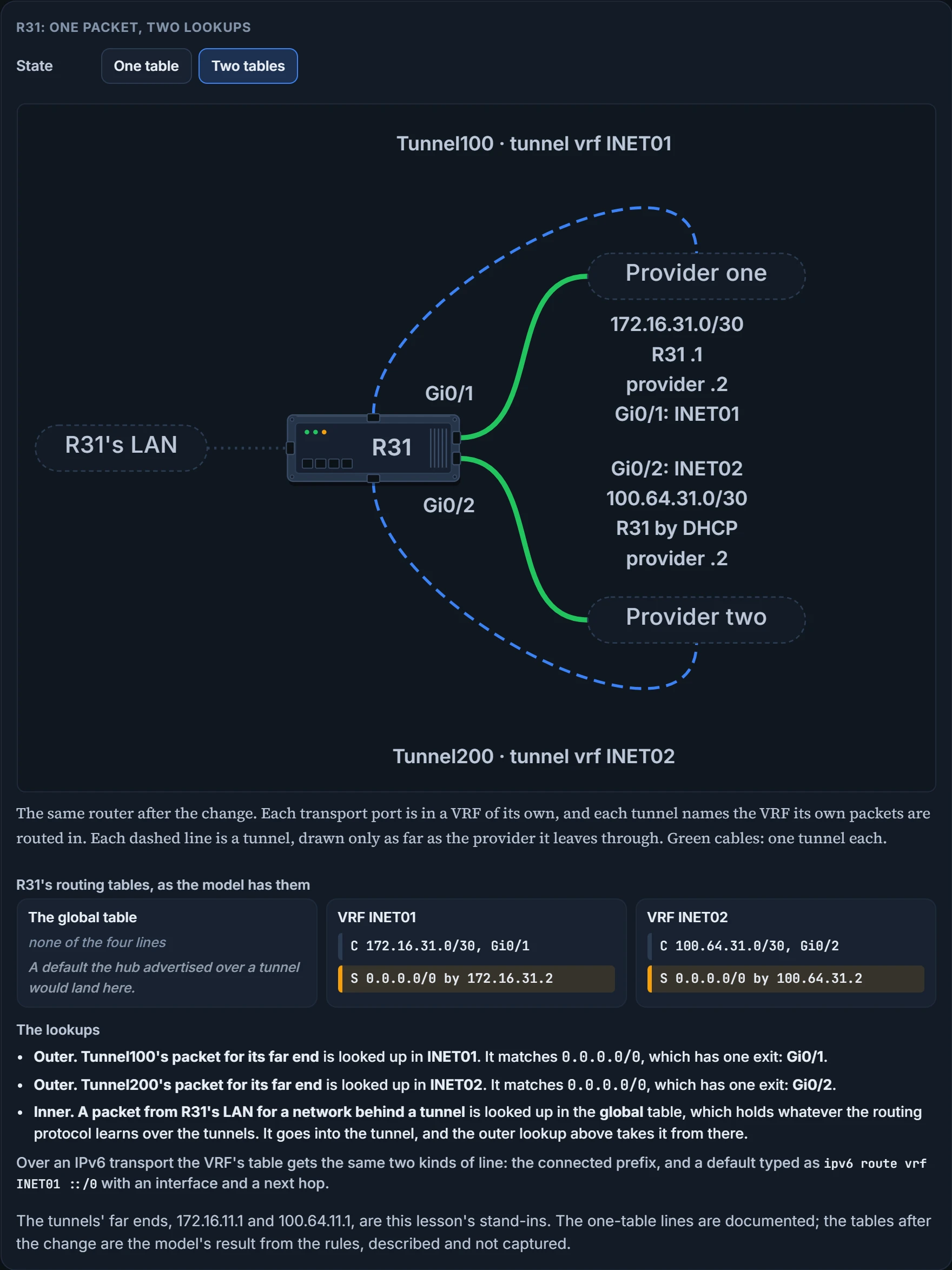
None of them. And yes.
Both connected routes left with their interfaces. Both defaults went with them: one is now typed into INET01 and the other is DHCP's, learned on an interface that lives in INET02. The table you've been reading since the first lesson of this course no longer has a route to either tunnel's destination, or to anything on the internet at all.
Tunnel 100's packets look up their destination in INET01, find one default with one exit, and leave by GigabitEthernet0/1. Tunnel 200's do the same in INET02 and leave by GigabitEthernet0/2. How would R31 know? There's nothing left to choose between.
Now bring back the hub's default. It arrives on Tunnel100, and Tunnel100's inner side is in the global table, so that's where the route goes. The transport's default is in INET01, where no routing protocol runs and nothing from the overlay can be installed. Two routes for 0.0.0.0/0 on one router, each the only one in its table. They can't fight. They never meet.
In IPv6 the steps are the same with the family changed. A hub whose transport is IPv6 carries these lines:
R11-Hub
vrf definition INET01
 address-family ipv6
 exit-address-family
interface Tunnel100
 tunnel mode gre multipoint ipv6
 tunnel vrf INET01
interface GigabitEthernet0/1
 vrf forwarding INET01
 ipv6 address 2001:DB8:172:16:11::1/126
ipv6 route vrf INET01 ::/0 GigabitEthernet0/1 2001:DB8:172:16:11::2
Beside the VRF's family and the port's address, two lines follow the transport: tunnel mode gre multipoint becomes tunnel mode gre multipoint ipv6, and the default route becomes ipv6 route vrf INET01 ::/0 with an interface and a next hop. If you ever meet an IPv6 default written with IPv4's zeros, ipv6 route vrf vrf-name 0.0.0.0 0.0.0.0 next-hop-ip, read it as a slip: ::/0 is the form to type.
How do you see an FVRF from the tunnel's side? show dmvpn detail. For R31's Tunnel100 it has an interface line ending VRF "" and under it Tunnel VRF "INET01". The two names sit on adjacent lines: empty quotes for the inner side, which we read as the global table, and INET01 for the outer. It proves which table each side of the tunnel is in. It doesn't prove either table has the routes it needs. For the exam, "front door VRF" is a term to know by name.
We haven't confirmed on a router, for this section: what a multipoint tunnel's interface shows when its outer table has no route to the hub; the global table after the move, which is the model's; and what the empty quotes mean.
Continue the lesson
The whole lesson, with its drawings and its questions. 3 more sections after the ones above.