
MPLS Layer 3 VPNs
Two customers can both use 10.0.0.0/24 across one provider. PE routers keep each customer in its own VRF; they carry customer routes to each other in MP-BGP, with a route distinguisher making identical prefixes unique. P routers in the core forward on labels and never read the customer addresses, and each packet carries two labels: one for the PE, one for the VPN.
By Arif, founder of Daveth · Updated
The full 18 min walkthrough is in Daveth Pro (Network). See what the plan opens
What this page answers
How does an MPLS Layer 3 VPN work?
The provider's PE routers keep each customer in a VRF, redistribute the customers' routes into MP-BGP and carry them to the other PEs; the core P routers only forward on labels. A route distinguisher keeps identical customer prefixes apart. Read it in “Carrying the routes across”
Why do MPLS VPN packets carry two labels?
The outer label, from LDP, gets the packet across the core to the right PE; the inner label tells that PE which customer's VRF the packet belongs to. Read it in “Third collision: the wire”
Two customers, one address
Two customers both use 10.0.0.0/24. Both hand their traffic to the same provider, over the same routers. How does it not collide?
(Each of them could be using all of 10.0.0.0/8. This lesson's example takes one /24 out of it.)
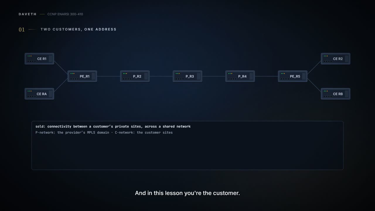
Start with what's being sold. MPLS Layer 3 VPNs provide peer-to-peer connectivity between private customer sites across a shared network. The setup: a provider, such as an ISP, runs an MPLS domain, and Customer A and Customer B both use that same MPLS domain to connect their own private sites together. Two names go with it. The MPLS domain is referred to as the P-network, and the customer sites are referred to as the C-network. And notice whose side you're on: this lesson is about how you can use an MPLS Layer 3 VPN to connect your private networks over your provider's public network. You're the customer here. Most of what follows happens on routers you'd never log in to.
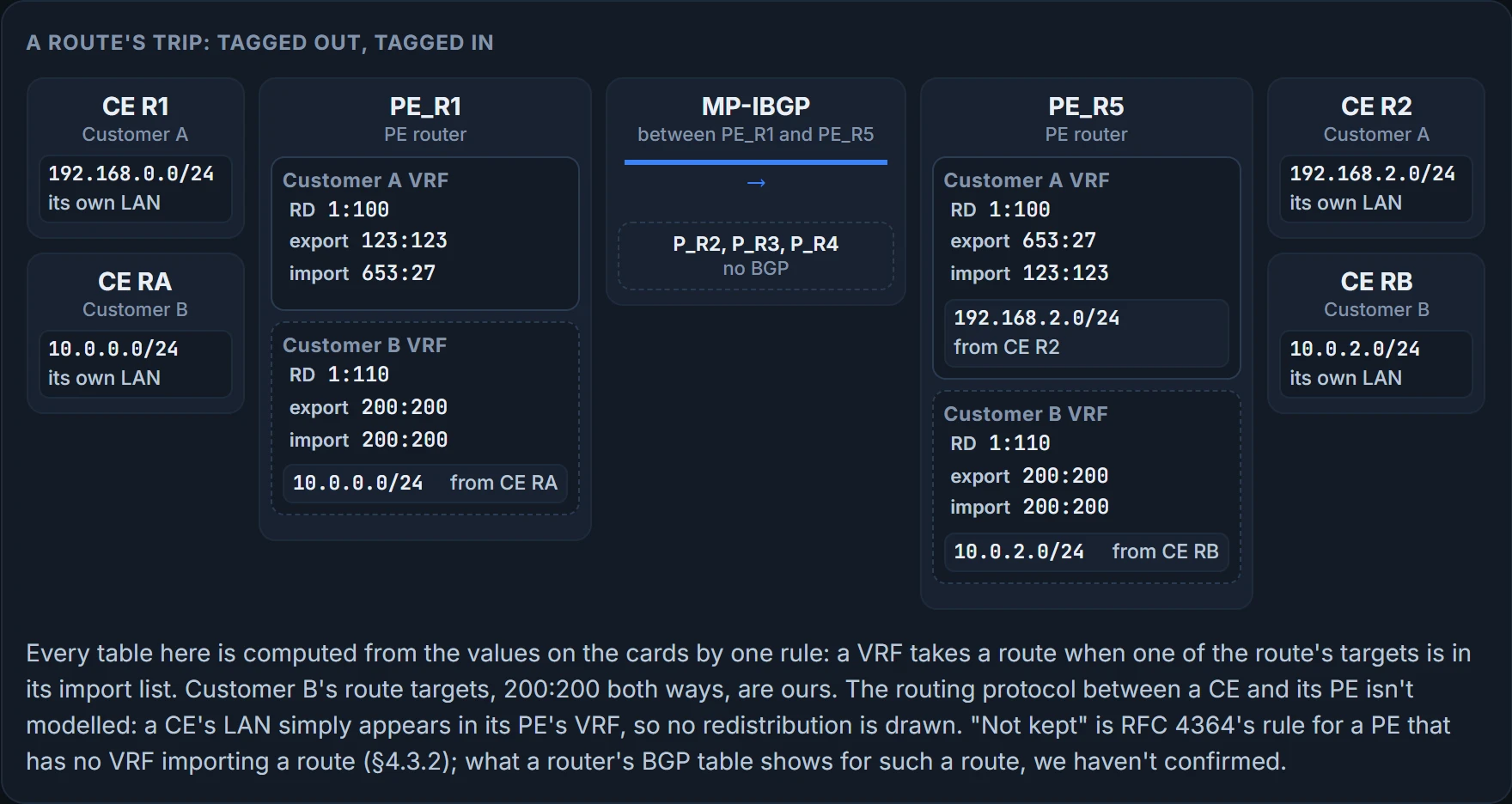
Three kinds of router, and what matters about each is what it knows. The drawing follows them.
The customer's routers are known as CE routers, for customer edge, and they do not run MPLS. More than that: they have no knowledge of MPLS, labels, or even VRF instances, which makes it easier for the customer to take advantage of what the provider's MPLS domain offers. The customer's routers know nothing about any of this. That isn't a gap in the design. It's the product.
The CE routers connect to the PE routers, for provider edge, of the MPLS domain. In this provider's network the PE routers, PE_R1 and PE_R5, are the ingress and egress LSRs for the MPLS domain: the last lesson's edge LSRs, the ones that put labels on and take them off.
The P routers, for provider, are P_R2, P_R3 and P_R4, and they're the intermediate LSRs of the domain. The middle of the row. Hold on to one thing about them: they forward on a label and never read the address under it.
Five provider routers, four customer routers: which of them know the customers' routes?
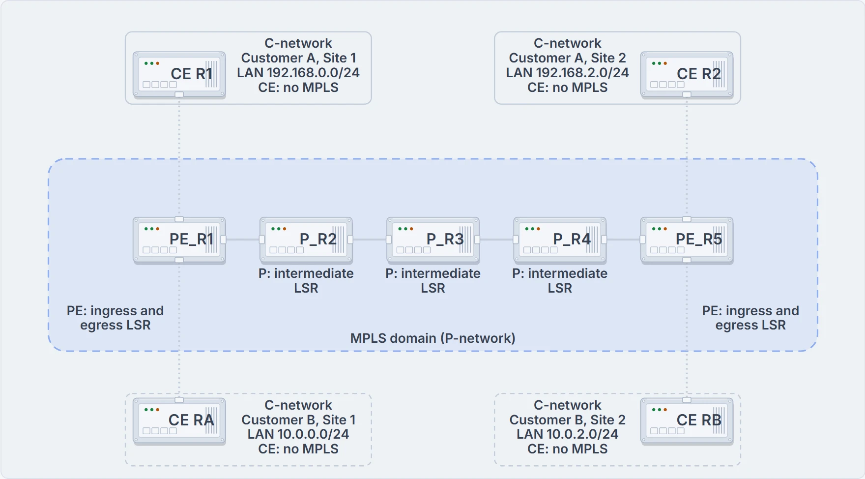
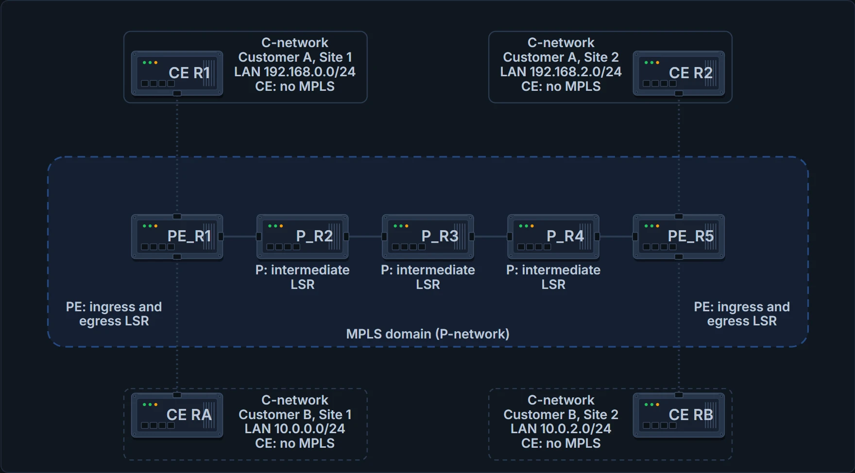
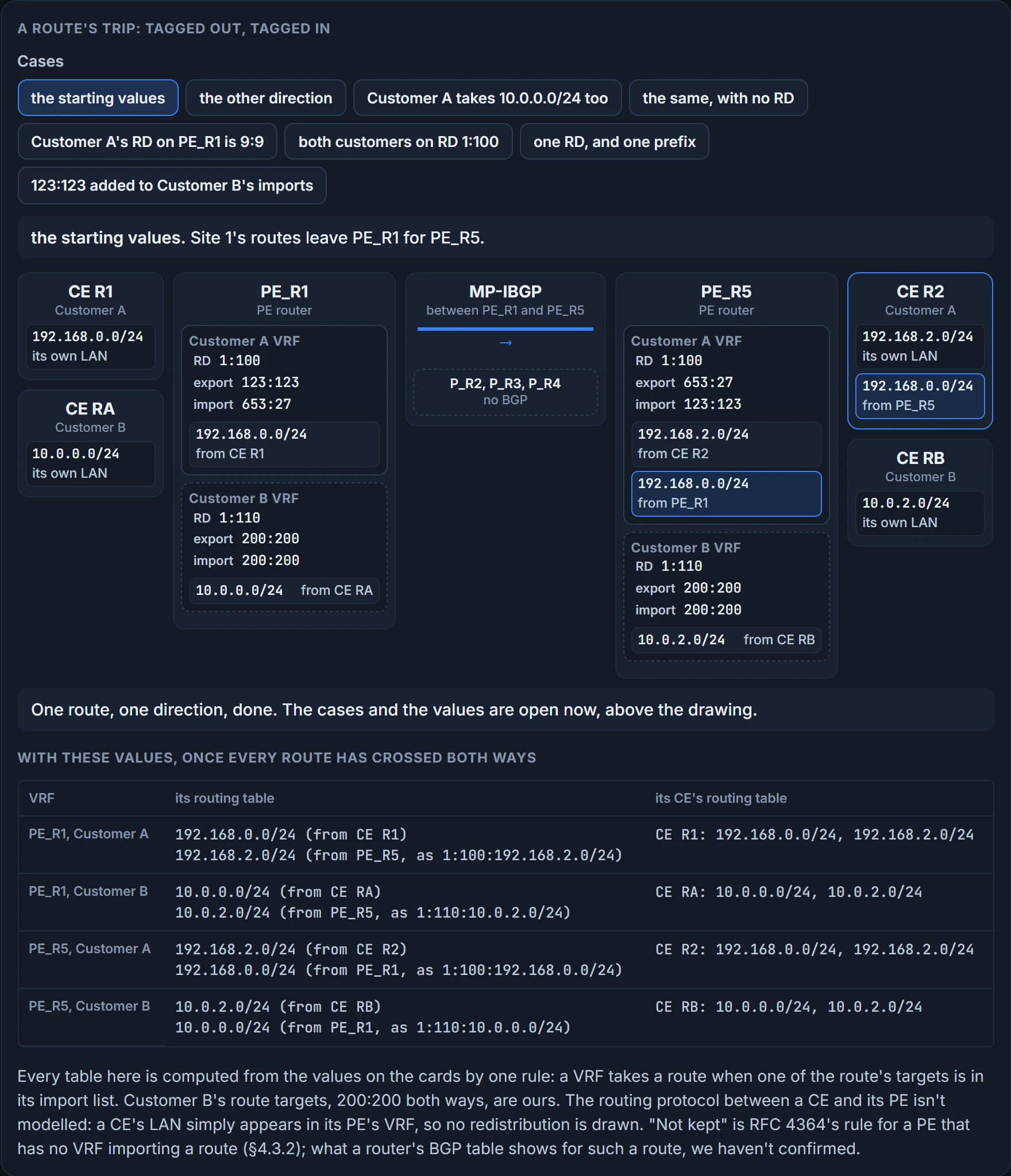
A provider's MPLS domain and two customers with two sites each. Only names and the four LANs matter here; no link addresses, loopbacks or AS numbers are needed. Customer A's sites have solid edges and Customer B's dashed.
CE routers hold their own customer's routes, and no labels.
The goal is plain. Customer A Site 1 and Customer A Site 2 exchange their local routing information over the MPLS domain and then forward traffic between the sites over it, and the same is true for Customer B's two sites. CE R1 has 192.168.0.0/24 and CE R2 has 192.168.2.0/24, both Customer A; CE RA has 10.0.0.0/24 and CE RB has 10.0.2.0/24, both Customer B.
One fact about a provider's edge router before going on. One that is connected to two different customers is configured with VRF instances, while the customers' CE routers each belong to a single enterprise and don't need any.
What does "peer-to-peer" mean here? Not that the sites tunnel to each other. This is the peer model: the service provider and the customer exchange Layer 3 routing information. More exactly, a CE router is a routing peer of the PE it's attached to, and it is not a routing peer of the CE routers at the other sites; they don't even need to know of each other (RFC 4364, §1.2). Your router talks routing to the provider's edge, and the provider does the rest.
And "private"? Private as in separate, not as in secret. An MPLS Layer 3 VPN adds no encryption, and no way to tell whether data was altered on the way (RFC 4364, §1.6); separation holds as long as the provider's configuration is right. Encryption arrives later in the course, with IPsec.
Now the claim this lesson tests. Because of the nature of the MPLS Layer 3 VPN, overlapping address spaces between customers is of no concern: Customer A and Customer B can be using the same private IP address space. So make them. Suppose Customer A also uses 10.0.0.0/24. One prefix, two owners. Follow it, and it runs into trouble in three places: inside PE_R1, inside BGP, and on the wire between the PE routers. Each place needs its own fix.
First collision: one router, two customers
PE_R1 has CE R1 on one interface and CE RA on another. Both tell it about 10.0.0.0/24. One routing table can't hold that as two different destinations.
You already own the fix. From the VRF lesson: a VRF is another routing and forwarding table on the same router, and every interface belongs to exactly one table. That's all a provider needs at this step.
In order to support multiple customers, the PE routers use VRF instances to isolate each customer's information and traffic from the other customers'. A different VRF instance is created on the PE routers for each customer, and the interface that connects to that customer's CE router is associated with the correct VRF. The lesson's drawing adds it as a second layer: two cards at each PE, a Customer A VRF and a Customer B VRF.
Then the routes have to get into those tables. The CE router and the PE router exchange IPv4 routes using a routing protocol such as RIP, EIGRP, OSPF or BGP, and the routes are placed in the customer-specific VRF table on the PE router. That's the subject of the lesson before last, a routing protocol running inside a VRF, seen from the provider's end. (The fuller list for this link has static routes on it too: BGP, RIPv2, EIGRP, OSPF or static.)
Look at it from your side of the link. From the customer's perspective, the PE router is simply another router in the customer's network, though it's under the control of the provider. You run OSPF, or EIGRP, or BGP, with it, exactly as you would with a router of your own. And all the P routers are hidden from the customer.
So on PE_R1 the first collision is over. In Customer A's table, 10.0.0.0/24 points at CE R1. In Customer B's table, 10.0.0.0/24 points at CE RA. Two entries, two tables. Which table a packet meets is decided before any lookup, by the interface it arrived on: the interface that connects to each customer's CE router was associated with that customer's VRF, and an interface belongs to exactly one.
That fixes one router. Customer A's other site is behind PE_R5, four hops away along the row, with three P routers in between, and a VRF is a local thing: the VRF lesson said even its name means nothing to the next router. How does a route in Customer A's table on PE_R1 get into Customer A's table on PE_R5?
Carrying the routes across
Before any detail, a question.
No. And you could have said so from the last lesson: an intermediate LSR forwards on the label and never reads the address under it.
So who does carry them? Once the PE routers learn routes from the CE routers, they redistribute the routes into MP-BGP so they can be exchanged with the other PE routers. When another PE router receives the routes, they're placed in the correct customer VRF instance, so they can be redistributed, if needed, and exchanged with the CE router there.
It's an important point: the P routers are not participating in BGP. Only the PE routers are. The PE routers form an MP-IBGP (Multiprotocol-Interior Border Gateway Protocol) neighborship with each other, and they exchange the routes over the underlying network, which is built with an IGP such as OSPF or IS-IS. Interior, because PE_R1 and PE_R5 are both inside the provider's AS: this is internal BGP, the BGP lessons' iBGP, a BGP connection between two speakers in the same autonomous system (RFC 4364, §4.3.2). The "MP" gets its turn in a moment.
So there are two layers of routing in the provider, and it's worth keeping them apart. The PE routers and the P routers all use a dynamic routing protocol to learn about every destination in the P-network. Only the PE routers use MP-IBGP, on top of that, to exchange the customers' routes. The lesson's drawing in the first section has a third layer for this: it draws the session passing over P_R2, P_R3 and P_R4 without touching them.
Put as a rule: P devices do not maintain any VPN routes, and a PE is only required to maintain VPN routes for the VPNs it's directly attached to. The reason is scale: if every backbone router had to hold routing information for every VPN, the number of sites would be limited by what one router can hold, so the P routers do not need to have any per-VPN routing information whatsoever (RFC 4364, §1.5).
Why "MP"? It's the multiprotocol BGP you used for IPv6: one session carrying routes for more than one address family, each family's routes and next hop riding in their own attribute, tagged with an address family identifier and a subsequent one (RFC 4760, §3). For these routes the pair is AFI 1, SAFI 128 (RFC 4364, §4.3.4). The IPv6 BGP lesson used the same machinery for IPv6. Here it carries a family you haven't met yet, and the next section builds it.
Two asides before moving on. Since MP-IBGP runs between the PE routers, you should consider BGP MD5 authentication between them for added security: you don't want someone hijacking your BGP sessions and introducing bogus routes or routers. And the drawing shows only a single path between the MP-IBGP routers, where most deployments have a multitude of paths, because they need resiliency. With several paths, you may want to consider load balancing between the MP-IBGP peers with maximum-paths ibgp number, typed in router BGP configuration mode. (The best-path lesson typed that command under the address family. Which of the two places a PE wants it for VPN routes, we haven't confirmed.)
Now put both customers' 10.0.0.0/24 into that one BGP session.
Second collision: one BGP, two identical prefixes
If all the customer routes are being redistributed into MP-BGP, how does BGP handle identical network prefixes that belong to different customers?
Badly, left alone. You know the habit from the best-path lesson: BGP compares paths to the same prefix and keeps one best. Here that would cost a customer a site: if two routes to the same prefix are really routes to different systems, BGP mustn't treat them as comparable, or it might install only one of them and make the other system unreachable (RFC 4364, §4). Without the fix, PE_R5 holds one 10.0.0.0/24 where there should be two.
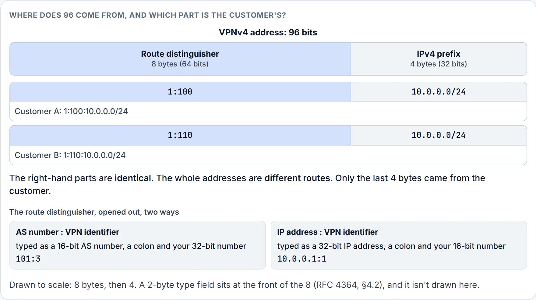
The fix is a longer name. BGP uses a route distinguisher, the RD, to expand the customer's IP prefix so that it includes a unique value that distinguishes it from the other identical prefixes. The RD is configured on the PE routers and used by them, on a per-customer VRF instance basis. And to keep things simple, the RD is used regardless of whether there are overlapping address spaces, so the RD is used all the time.
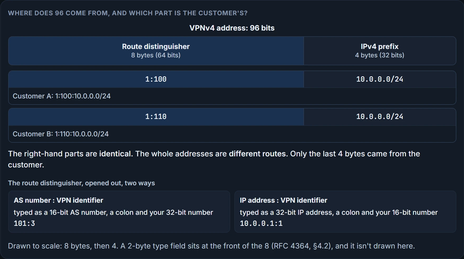
The arithmetic: the unique 64-bit RD is prepended to the 32-bit customer prefix, the IPv4 route, to create a 96-bit unique prefix called a VPNv4 address. That VPNv4 address is what the MP-IBGP neighbors exchange. It's the new address family from the last section.
Open it up. A VPNv4 address is a route distinguisher of 8 bytes followed by an IPv4 address of 4 bytes, and the RD itself is laid out one of two ways: an AS number with a VPN identifier, or an IP address with a VPN identifier. Those are the two forms you can type: a 16-bit AS number, a colon and your 32-bit number, for example 101:3, or a 32-bit IP address, a colon and your 16-bit number, for example 10.0.0.1:1.
In this network the Customer A VRF instance uses an RD of 1:100 and the Customer B VRF instance uses an RD of 1:110. RDs are configured with the rd rd-value command in VRF configuration mode for the customer's VRF, so for Customer A it would have been rd 1:100. Prepend those RDs to the prefixes and you get a VPNv4 route of 1:100:192.168.0.0/24 and a VPNv4 route of 1:110:10.0.0.0/24.
Now the collision. Customer A also chooses to use 10.0.0.0/24 and advertises it to its other site. This is where the RDs keep everything unique: Customer A has the VPNv4 route 1:100:10.0.0.0/24 and Customer B has 1:110:10.0.0.0/24. To BGP those are two different destinations. PE_R5 holds both. Second collision over.
Not a collision: who gets the route
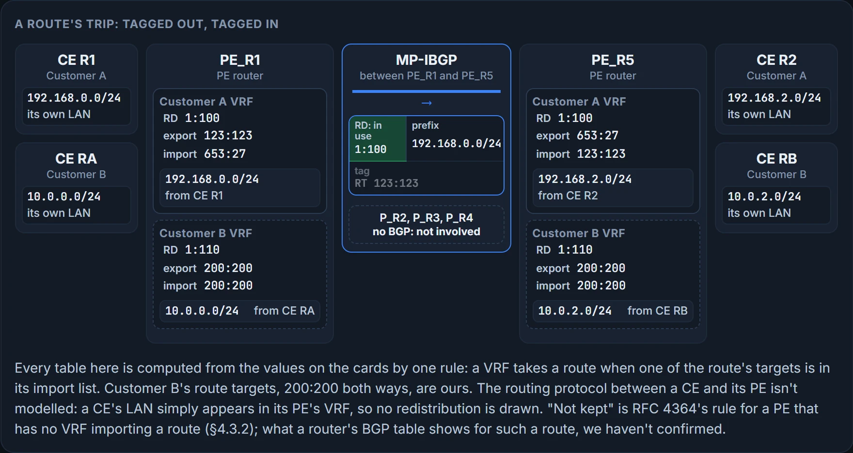
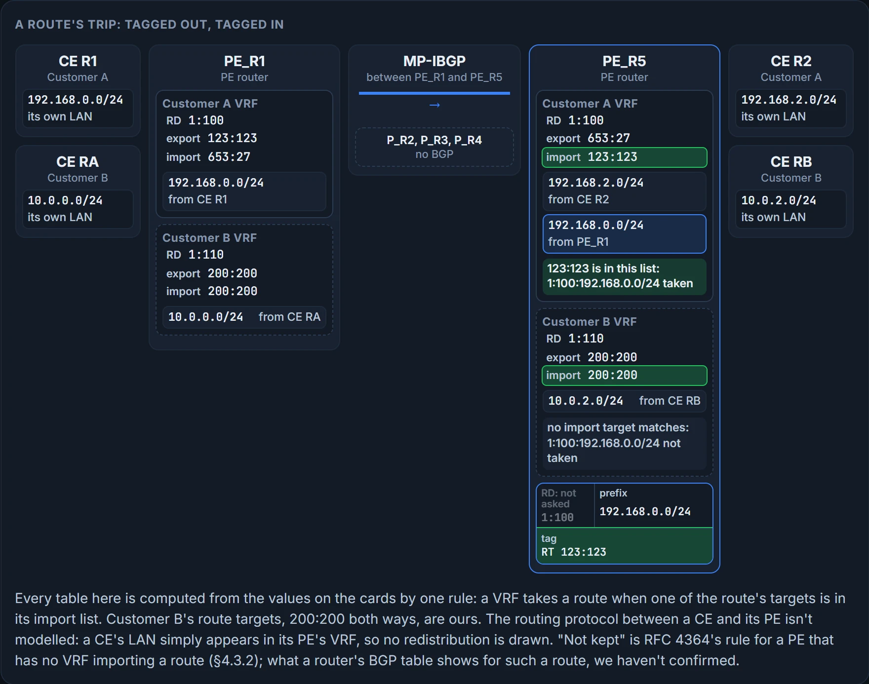
Take a route you've already named: 1:100:192.168.0.0/24, Customer A's Site 1, sent by PE_R1 toward PE_R5. The figure steps the route across: watch what PE_R5 looks at when it arrives.
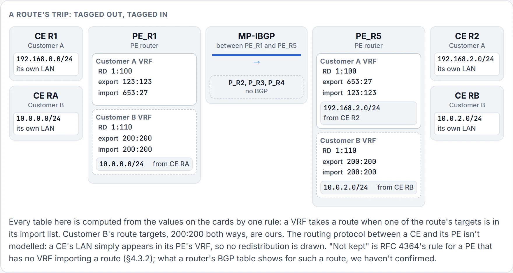
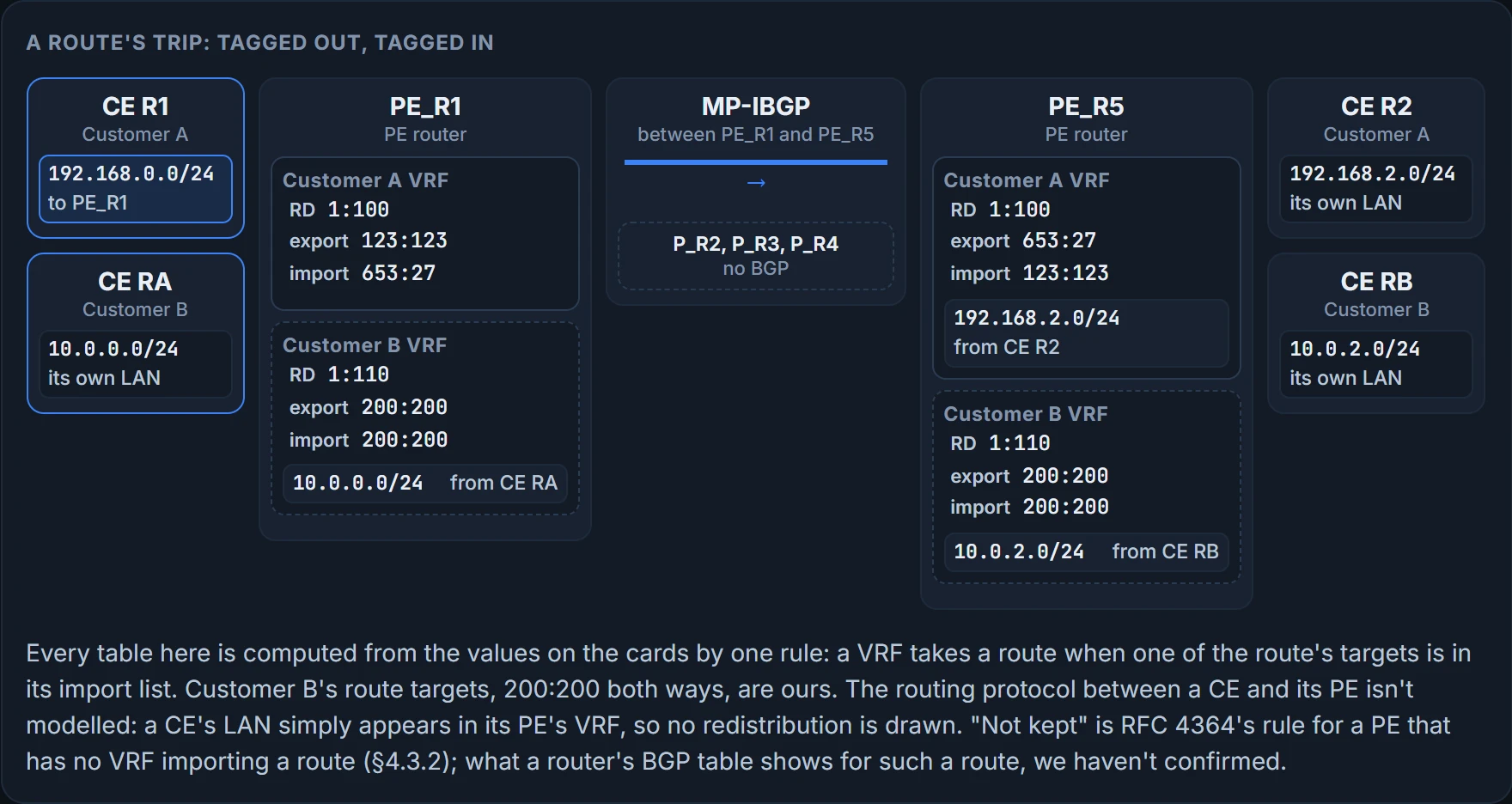
Step 1 of 7 Ready. One route, one direction: Customer A's 192.168.0.0/24, from CE R1 toward PE_R5.
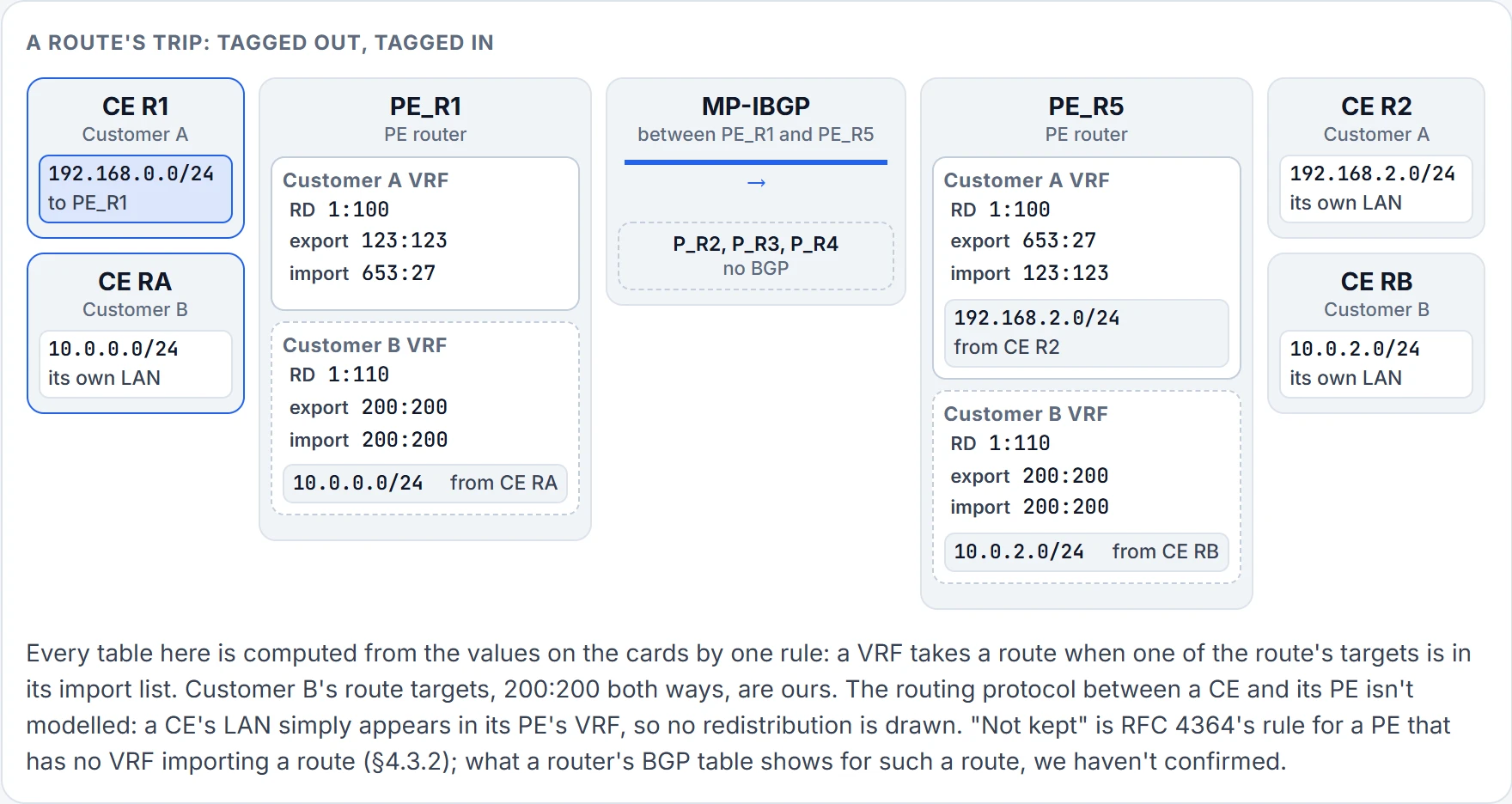
Step 2 of 7 Step 1. CE R1 and PE_R1 exchange routes with a routing protocol: 192.168.0.0/24 is on the way to the PE.
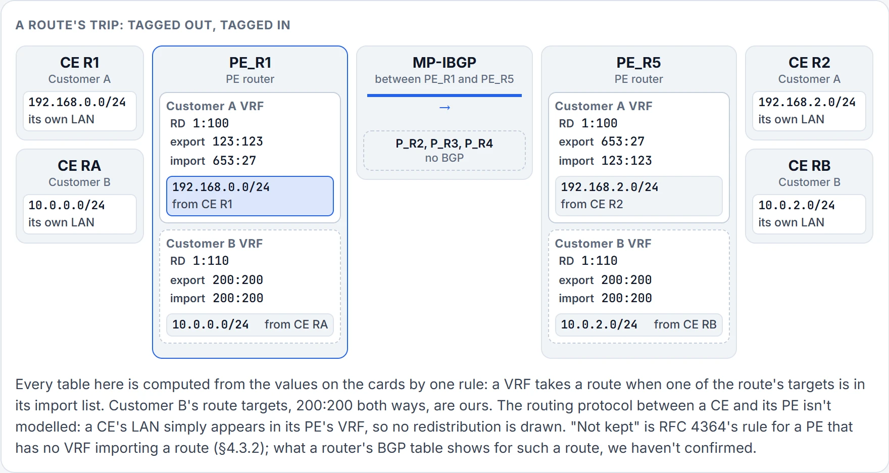
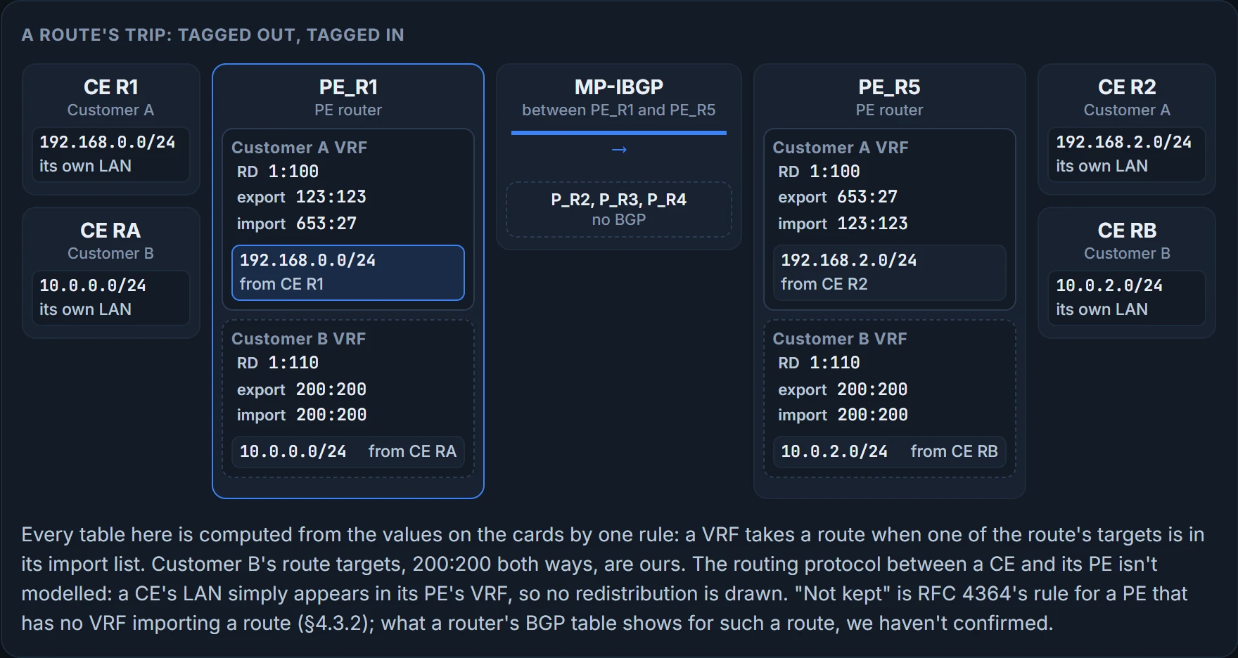
Step 3 of 7 Step 2. PE_R1 places it in the table of the VRF its interface belongs to, Customer A's. It's still a plain IPv4 route.
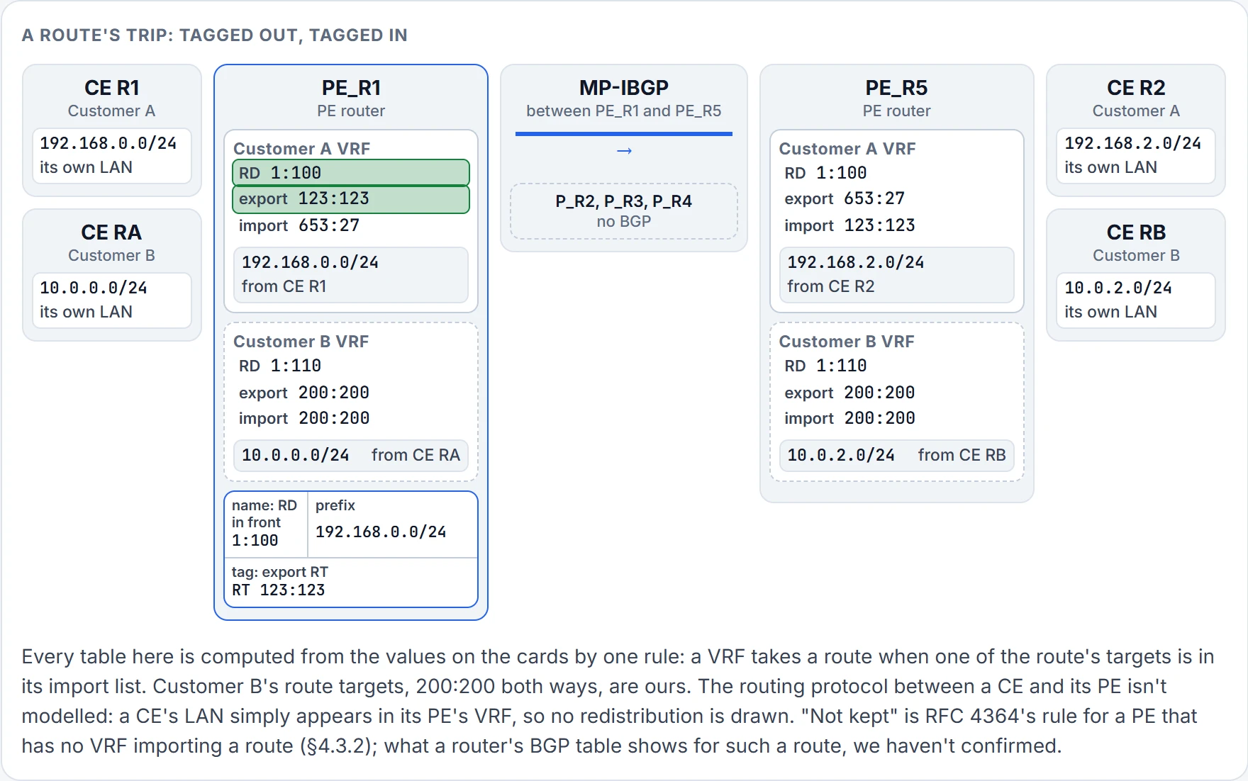
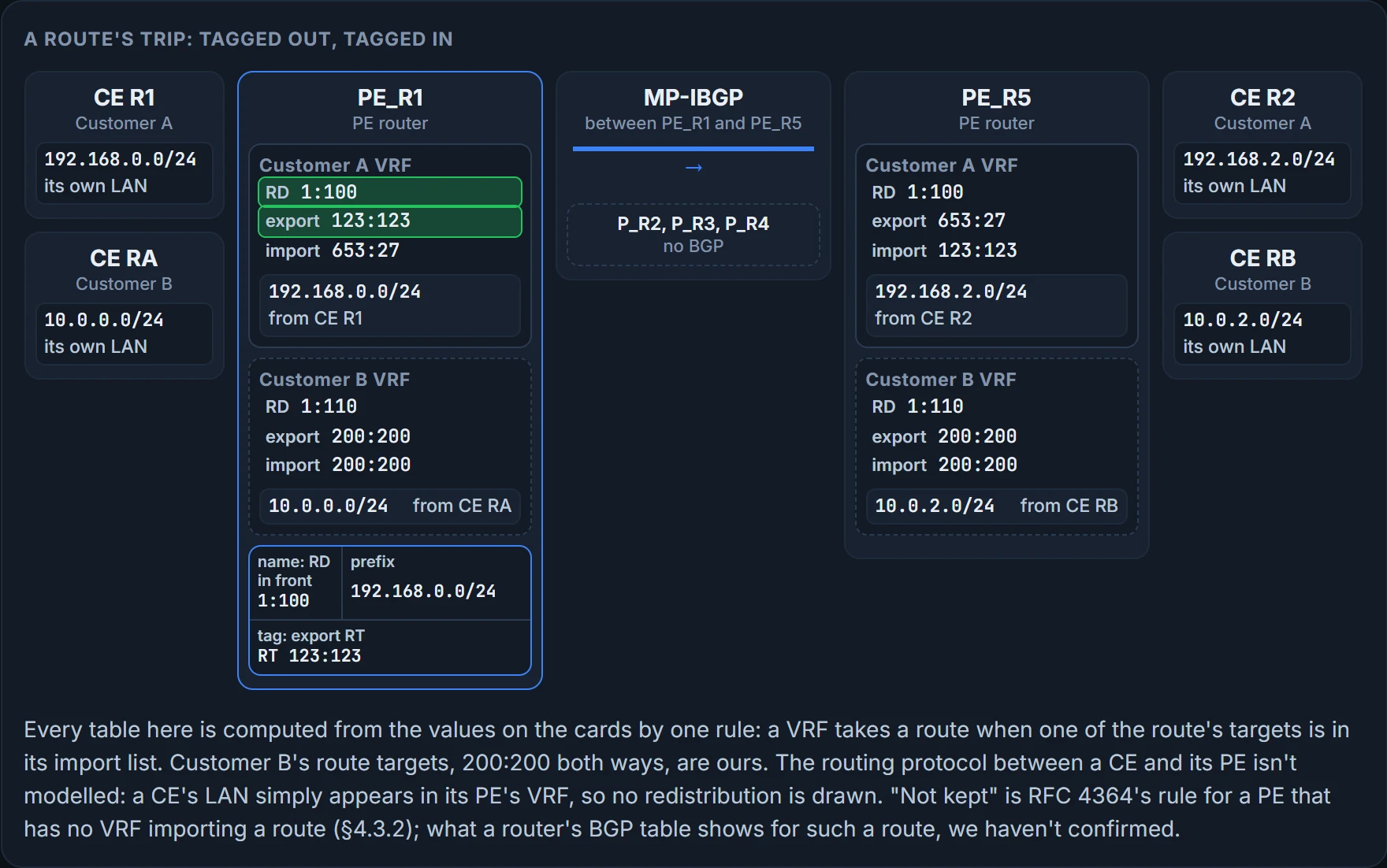
Step 4 of 7 Step 3. It leaves the VRF for MP-BGP as a VPNv4 route, and two things go on. The name: the VRF's RD in front, 1:100:192.168.0.0/24. The tag: the VRF's export target, 123:123 on 192.168.0.0/24.
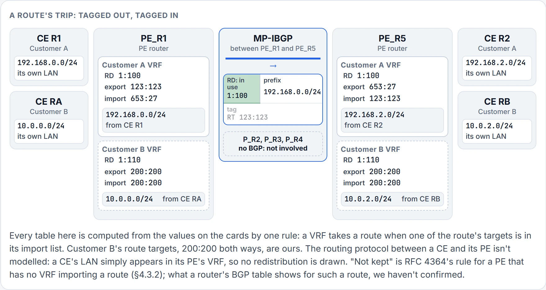
Step 5 of 7 Step 4. PE_R1 sends it to PE_R5 over their MP-IBGP session. The RD is in use here: it's part of the name BGP files each route under, and it's how identical prefixes stay apart. The tag rides along as an attribute. P_R2, P_R3 and P_R4 aren't in BGP and never see it.
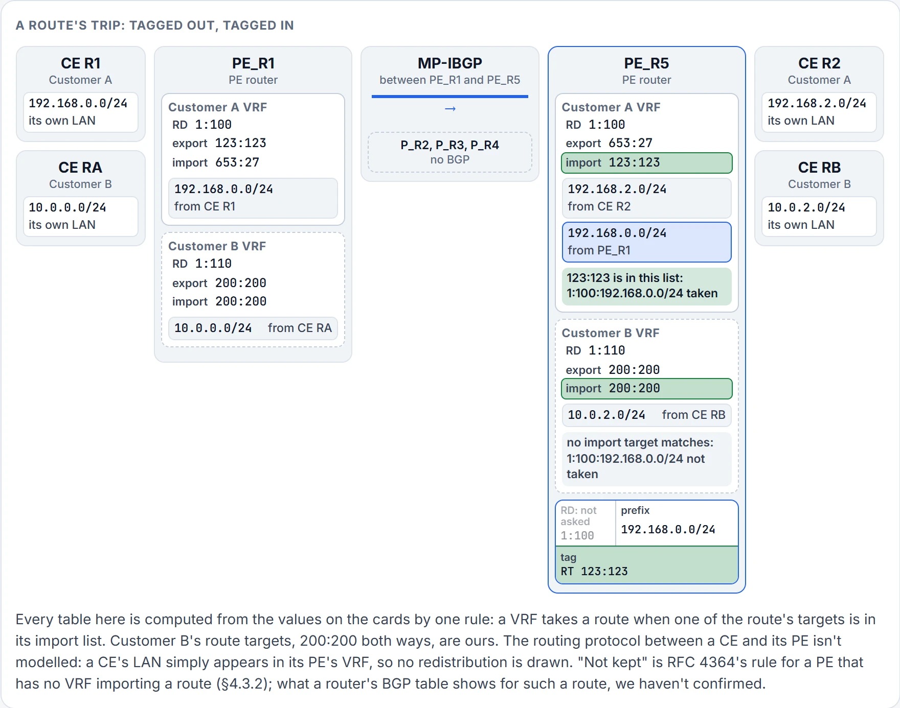
Step 6 of 7 Step 5. PE_R5 compares each route's tag with each VRF's import list, and that comparison alone decides. 1:100:192.168.0.0/24 carries 123:123: taken into Customer A's table, whose import list has 123:123. The RD isn't asked.
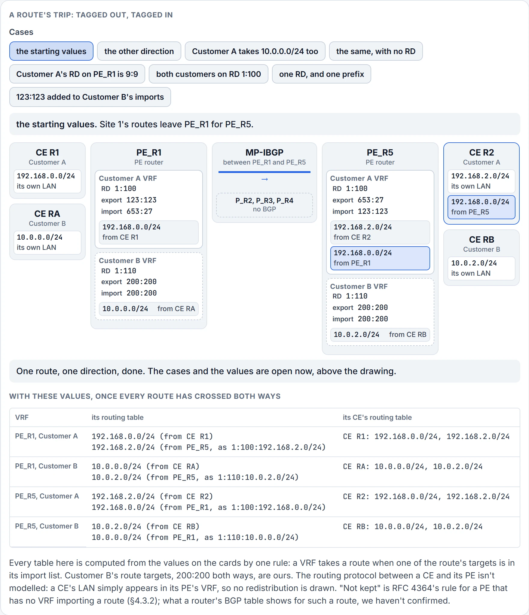
Step 7 of 7 Step 6. PE_R5 passes 192.168.0.0/24 to CE R2, as an ordinary IPv4 route. The name and the tag stay behind on the PE. PE_R1 keeps 1:100:192.168.2.0/24 and 1:110:10.0.2.0/24 from PE_R5. PE_R5 keeps 1:100:192.168.0.0/24 and 1:110:10.0.0.0/24 from PE_R1.
No. It's the natural guess, and it's the one thing in this lesson to unlearn.
Start with the number itself. 1:100 looks as if it means something: customer 100, maybe, or site 1. It doesn't have to mean anything. RFC 4364: an RD is simply a number, and it does not contain any inherent information; it does not identify the origin of the route or the set of VPNs to which the route is to be distributed. Its purpose is solely to allow one to create distinct routes to a common IPv4 address prefix, and other means are used to determine where to redistribute the route (§4.1).
Other means. You just watched them at step 5: PE_R5 held the route, it has two VRFs, and the RD wasn't what it compared. The real question is this one: how does the provider ensure that what has been exported from a customer VRF instance on one PE router is sent across the MPLS environment and successfully imported into the correct customer VRF instance on another PE router? The answer: route targets.
RTs are used to control the import and export process for customer VRF instance routes. An RT, like an RD, is configured in the VRF configuration for the customer VRF instance. The VRF lesson's help list named the two commands, rd and route-target, and stopped there. Their descriptions are new: rd, Specify Route Distinguisher, and route-target, Specify Target VPN Extended Communities. That second description is exact. A route target travels as a BGP attribute of the route, encoded as an extended community: the policy lesson's communities, in a larger format (RFC 4364, §4.3.1).
Follow one route, one direction. On PE_R5, for the Customer A VRF, you might configure an export RT of 653:27 with route-target export route-target-number and an import RT of 123:123 with route-target import route-target-number. On PE_R1 you'd then do the reverse: an export RT of 123:123 and an import RT of 653:27 for the Customer A VRF. When PE_R1 exports the customer's VRF routes, it attaches the RT 123:123, so that when PE_R5 receives them it knows they belong to the Customer A VRF, because that VRF was configured with the import RT 123:123, and it places the routes in the Customer A VRF table. The other direction works the same way: PE_R5 attaches 653:27 to Customer A's routes, and PE_R1 imports them into its Customer A VRF because it has the import RT 653:27.
So the two values on one router don't have to be equal. The lesson before last left you a rule for this one: the import and export values on your own router can differ, but the router that is importing has to match the router that is exporting; export with 1:5 on one router and the other must import 1:5, or the export and import process fails. So the comparison that decides an import is always between the same two things: the targets on the route, which the exporting VRF attached, and the import list of the VRF that's deciding. Nothing stops one VRF from exporting and importing the same value. route-target both does exactly that in one line.
RFC 4364 states the rule in a form you can apply to anything: a VPN route is only eligible for installation in a particular VRF if there is some route target that is both one of the route's route targets and one of the VRF's import targets (§4.3.1). That's the whole test. Look at what isn't in it.
The RD isn't in it. Change Customer A's RD on PE_R1 from 1:100 to 9:9 and leave everything else: PE_R5's Customer A table is exactly what it was. Give both customers the same RD, with no overlapping prefix: each table still gets only its own routes. Both are cases in the figure. Now change one import target: open "Change the values yourself" under the cases, type 5:5 as PE_R5's Customer A import, and that table keeps its own site's network and loses its remote route.
Two jobs, then. The RD is part of the route's name. It makes two identical prefixes into two different routes, and it does nothing else. The RT is a tag on the route. It decides which VRFs take the route in, and it has no say in whether two routes are the same. Names make routes distinct; tags get them delivered. A route has exactly one RD, and it can carry several RTs.
What about the other customer? The provider configures unique RTs for the Customer B VRF instances, so that Customer B's routes are exported and imported correctly and don't end up in the wrong VRF instance. You'll hear the conclusion put this way: RTs must be unique within the MPLS environment. Read "unique" as per customer VPN, not per router or per VRF: 123:123 has to appear on both PE routers or nothing would be imported at all. The simplest design gives every VRF of one closed group a single route target, as both its import and its export target, and gives that target to no other VRF (RFC 4364, §4.3.5). So the default to expect is that no customer's export target appears in another customer's import list: add 123:123 to Customer B's imports on PE_R5 and Customer A's Site 1 is in Customer B's routing table. A provider does that on purpose only where two VPNs are meant to share routes: a VRF that holds a service both customers use, for instance.
One reason the two get mixed up is a habit: you'll often see the route target set to the same digits as the RD. Same digits, two jobs. When they're always equal, it's easy to believe one of them is doing both.
Here's the whole trip you just stepped through, as a list:
- The CE router and the PE router exchange routes using a dynamic routing protocol such as OSPF, EIGRP or BGP.
- The PE router places the customer-specific routes in the customer-specific VRF table.
- The routes in the customer's VRF table are redistributed into MP-BGP as VPNv4 routes, if an IGP is used between provider and customer. If BGP is used between them, redistribution isn't needed: they're already BGP routes.
- The PE routers exchange VPNv4 routes over their MP-IBGP peering.
- The receiving PE router redistributes the VPNv4 routes as OSPF or EIGRP into the customer-specific VRF table, if an IGP is used between provider and customer. If BGP is used, the routes go into the customer-specific VRF table without redistribution.
- The PE router and the CE router exchange routes using a dynamic routing protocol such as OSPF, EIGRP or BGP.
Now set the two fields against those steps, because each one is used at a different step.
Steps 1 and 2: neither field is on the route yet. What sits in the VRF table is a plain IPv4 route.
Step 3: both go on. The RD goes in front of the prefix, which makes the VPNv4 route, and the VRF's export targets are attached to it.
Step 4: the RD is in use. It's part of the address BGP is carrying, so Customer A's 10.0.0.0/24 and Customer B's cross as two routes and arrive as two. The RT crosses with the route as one of its attributes, and it isn't what keeps the two apart.
Step 5: the RT is in use. The receiving PE compares the route's targets with each VRF's import list, and that comparison alone decides which tables take the route. (The PE makes the same comparison as the route comes in, to discard what none of its VRFs would take: RFC 4364, §4.3.2.) The RD is still on the route and has no say in the choice. Once a VRF takes the route it's an IPv4 route in that table again, and the RD's work is over: the chosen routes are converted back into IP routes (RFC 4364, §4.3).
Step 6: what the PE passes to the CE is an IPv4 route.
So the RD is used, at step 4, to keep routes distinct. It's never used to choose who imports.
The routes are where they should be. CE RA knows about 10.0.2.0/24, and CE R1 doesn't. Now send a packet.
Third collision: the wire
CE RA sends a packet to a host in 10.0.2.0/24. PE_R1 receives it on Customer B's interface, looks in Customer B's table and finds the route: it came from PE_R5.
Try the obvious thing. PE_R1 pushes the LDP label that leads to PE_R5 and sends the packet into the core.
A bare IP packet arrives, because P_R4 popped the label one hop early, as PE_R5 asked it to (the last lesson's penultimate-hop popping). It's addressed to 10.0.2.something and it came in on a core interface, which belongs to no customer's VRF. So PE_R5 looks in its global table, the only one a core interface belongs to, and no customer's route is there. Dropped. And remember the overlap: a packet for 10.0.0.0/24 could be Customer A's or Customer B's, and the address can't say which. That's the third collision. The packet has to carry something that says whose it is, all the way across.
So, for the MPLS domain to forward traffic, a label stack is required. Specifically, two labels are required for traffic to be successfully forwarded through the MPLS domain. The first label that's attached to the packet is a VPN label, and the second label that's attached is the LDP label. First attached means underneath: the VPN label is the bottom of the stack, next to the IP packet, and the LDP label is on top, where the next router looks. The same order, told from the stack's side: the label for the VPN route goes on first, as the sole label, and then the label that gets the packet to the other PE is pushed on as the packet's top label (RFC 4364, §5). (The last lesson's bottom-of-stack bit, the S bit, marks the bottom one.) So a label stack, here, is two labels, the VPN label and the LDP label, added to a packet to forward it through the MPLS Layer 3 VPN.
When the IP packet arrives at the ingress PE router, that PE router attaches both labels. Each label has one reader. The egress router uses the VPN label to determine customer specifics about the packet and what should be done with it. The LDP label is used for label switching from PE to PE in the MPLS domain. And they're learned differently: VPN labels are learned from PE routers over the MP-IBGP peering, and the LDP labels are learned the way the last lesson described.
If you've ever worked in a shared office building, it's how the post gets to you. The courier reads the building's address and nothing else. The mailroom reads the line underneath, "Customer B, Room 10", and it's the only place that knows there are two Room 10s. The courier is every P router, the mailroom is PE_R5, and the comparison stops at the street: a real address doesn't get rewritten at every corner, and nobody tears it off one stop before the building. Both of those happen here.
Continue the lesson
The whole lesson, with its drawings and its questions. The rest of this section and 3 more after it.