
VRF-Lite
Two tenants both numbered their offices 10.1.1.0/24, and one switch routes for both. Multi-VRF CE gives each its own routing table, so overlapping addresses can be reused, with no MPLS. Nothing in the packet says which tenant it belongs to: the switch picks the table by the interface the packet arrived on, a routed port or an SVI, through its VRF.
By Arif, founder of Daveth · Updated
The full 5 min walkthrough is in Daveth Pro (Network). See what the plan opens
What this page answers
How does a switch know which VRF a packet belongs to?
By where it arrived. The input interface's VLAN, a routed port's internal VLAN or an SVI's VLAN, maps to a policy label for its VRF, and the switch looks up that VRF's routing table. Read it in “What picks the table”
What is VRF-Lite used for?
Keeping several networks separate on one device: Multi-VRF CE supports two or more VPNs with overlapping IP addresses, each in its own table, without MPLS. Read it in “Two tenants, one address”
Two tenants, one address
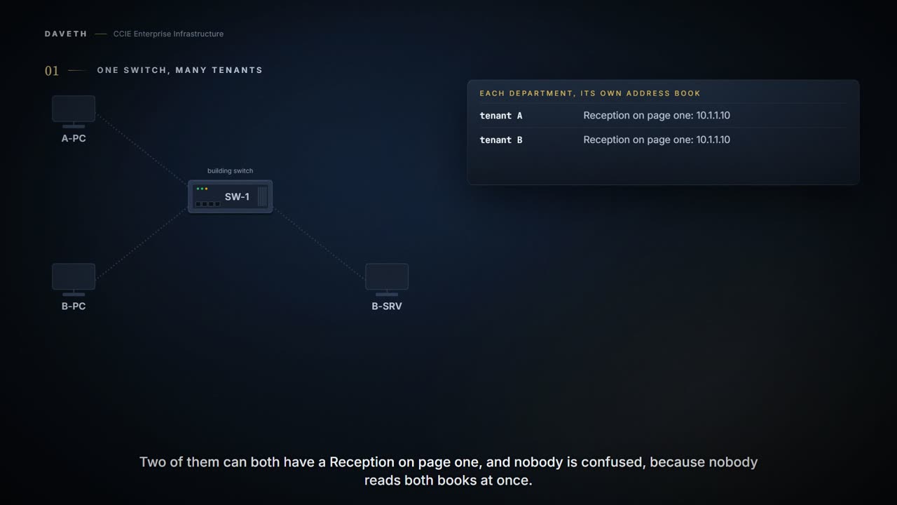
Each department keeps its own address book. Two of them can both have a Reception on page one, and nobody is confused, because nobody is reading both books at once.
A building owner runs one switch, SW-1, for every tenant. Tenant A and tenant B both numbered their offices 10.1.1.0/24, and both have a PC at 10.1.1.10. Tenant B also has a server room on its own port. How can one switch route for both?
Multi-VRF CE allows a service provider to support two or more VPNs with overlapping IP addresses.
The page calls the feature multi-VRF CE and explains it with service providers and VPNs. In this building, the service provider is a switch in a riser cupboard.
A routing table is the list of networks a router knows and where each one is. A VRF is a second, separately named routing table inside the same switch. Each tenant gets one.
Because customers use different VRF tables, the same IP addresses can be reused. The switch does not use Multiprotocol Label Switching (MPLS) to support VPNs.
Configuration: two tenants and the building network, in the form this command takes; the VRF names, RDs and addresses are this course's own.
SW-1# configure terminal
SW-1(config)# ip vrf TENANT-A
SW-1(config-vrf)# rd 65000:1
SW-1(config-vrf)# route-target both 65000:1
SW-1(config-vrf)# ip vrf TENANT-B
SW-1(config-vrf)# rd 65000:2
SW-1(config-vrf)# route-target both 65000:2
SW-1(config-vrf)# interface GigabitEthernet1/0/1
SW-1(config-if)# no switchport
SW-1(config-if)# ip vrf forwarding TENANT-A
SW-1(config-if)# ip address 10.1.1.1 255.255.255.0
SW-1(config-if)# interface GigabitEthernet1/0/2
SW-1(config-if)# no switchport
SW-1(config-if)# ip vrf forwarding TENANT-B
SW-1(config-if)# ip address 10.1.1.1 255.255.255.0
SW-1(config-if)# interface GigabitEthernet1/0/5
SW-1(config-if)# no switchport
SW-1(config-if)# ip vrf forwarding TENANT-B
SW-1(config-if)# ip address 10.2.2.1 255.255.255.0
SW-1(config-if)# interface GigabitEthernet1/0/3
SW-1(config-if)# no switchport
SW-1(config-if)# ip address 10.9.9.1 255.255.255.0
SW-1(config-if)# end
Proves: The configuration proves which table each interface feeds. Does not prove: what any table holds, or that every tenant interface was placed. An interface with no VRF line still feeds a table: the global one.
B-SRV sends a packet to 10.1.1.10. Two PCs have that address.
Multi-VRF CE uses input interfaces to distinguish routes for different VPNs and forms virtual packet-forwarding tables by associating one or more Layer 3 interfaces with each VRF.
Computed from the state, where packets go. No command prints it in this form.
from   to         table used result
B-SRV  10.1.1.10  TENANT-B   out Gi1/0/2
A-PC   10.2.2.10  TENANT-A   no route
A-PC   10.9.9.20  TENANT-A   no route
Look at the first row: from B-SRV, the table used is TENANT-B, and the packet leaves on Gi1/0/2 toward B-PC. The interface the packet arrived on decides which table is searched, so A-PC is never a candidate. The second row runs the other way: A-PC has no route to tenant B's servers at all.
What picks the table
If nothing in the address says which tenant, what does the switch actually use?
VLAN IDs from different VRFs are mapped into different policy labels, which are used to distinguish the VRFs during processing. If the packet is received from a routed port, the port internal VLAN ID number is used; if the packet is received from an SVI, the VLAN number is used. When the switch receives a packet from a VPN, the switch looks up the routing table based on the input policy label number.
Watch where the VLAN number comes from in the middle quote: a routed port supplies an internal one, an SVI its own.
A policy label is a number inside the switch, taken from the VLAN the packet came in on. Each VRF's VLANs get their own label. So the table is settled by where the packet arrived before the destination is ever looked up.
Interfaces in a VRF can be either physical, such as Ethernet ports, or logical, such as VLAN SVIs, but an interface cannot belong to more than one VRF at any time. Multi-VRF CE interfaces must be Layer 3 interfaces.
Read the end of the first quote: an interface cannot belong to more than one VRF at any time. If the interface picks the table, one interface in two tables would pick two, and the page rules that out.
Building one
What does it take to create a VRF and put an interface in it?
From elsewhere: the page's VRF. The names, numbers and addresses come from elsewhere, not from this scenario.
Device(config)#ip vrf v11
Device(config-vrf)#rd 800:1
Device(config-vrf)#route-target export 800:1
Device(config-vrf)#route-target import 800:1
Look at the numbers: the RD and both route targets are 800:1.
Creates a VRF table by specifying a route distinguisher. The route-target-ext-community should be the same as the route-distinguisher entered in Step 4.
A route distinguisher, or RD, is the value the page creates the VRF's table with. Route targets, in the page's words, list the members of a VPN community; how routes move between tables is later work (1.2.f and 3.2.b), and the page says to make them match the RD here.
From elsewhere: an SVI placed in a VRF. The names, numbers and addresses come from elsewhere, not from this scenario.
Device(config)#interface vlan10
Device(config-if)#ip vrf forwarding v11
Device(config-if)#ip address 38.0.0.8 255.255.255.0
Associates the VRF with the Layer 3 interface. To use multi-VRF CE, you must have the Network Advantage license enabled on your switch.
Notice the order in the page's examples: the VRF line comes before the address, every time. Whether placing an interface in a VRF removes an address that was already there isn't stated on this page, so this course doesn't claim it.
The same page also uses a second form in its NTP steps:
From elsewhere: the other form. The names, numbers and addresses come from elsewhere, not from this scenario.
Device(config-if)#vrf forwarding A
Continue the lesson
The whole lesson, with its drawings and its questions. 5 more sections after the ones above.