
GRE tunnels, and recursive routing
GRE wraps a packet in a new IP header, protocol 47, addressed to the far end of the tunnel, so the network between routes it without looking inside. Configure interface tunnel with a tunnel source, a tunnel destination and an overlay address. Recursive routing happens when the route to the tunnel's own destination is learned through the tunnel.
By Arif, founder of Daveth · Updated
The full 8 min walkthrough is in Daveth Pro (Network). See what the plan opens
What this page answers
How do you configure a GRE tunnel?
interface tunnel number, tunnel source with a local interface or address, tunnel destination with the far router's underlay address, and an ip address for the overlay. The tunnel comes up when the router has a route to the tunnel destination. Read it in “4.1 What GRE puts round a packet”
What is GRE recursive routing?
When a router learns the route to its tunnel's destination through the tunnel itself, as when OSPF over the tunnel advertises the underlay addresses. IOS logs %TUN-5-RECURDOWN and disables the tunnel, the route disappears, the tunnel comes back, and the cycle repeats: the tunnel flaps. Read it in “4.1 What GRE puts round a packet”
4.1 What GRE puts round a packet
Generic Routing Encapsulation (GRE) carries "a wide variety of network-layer protocols by encapsulating and forwarding packets over an IP-based network". It was built to carry non-routable legacy protocols such as IPX across IP (quiz Q2: true), and today it's mostly an overlay for IPv4 and IPv6. People use it to cross a firewall or ACL, to join discontiguous networks, to build VPNs, and as "networking duct tape for bad routing designs".
The guide calls GRE "networking duct tape", which is the most honest thing anyone has written about a tunnelling protocol.
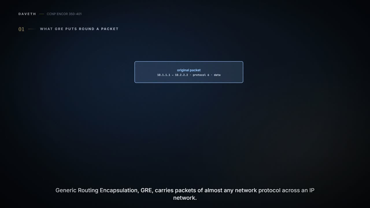
The router adds a new IP header whose destination is the far end of the tunnel, plus a GRE header, around the original packet; the network in between routes on the new header "without inspection of the packet's payload", and the far end strips it off (de-encapsulation). The outer header says protocol 47, GRE, where the original said 1 (ICMP), 6 (TCP) or 17 (UDP) (Figure 16-1). The basic GRE header is four bytes: a checksum-present bit, reserved bits, a version and the payload's protocol type (0x800 for IPv4); a checksum, and RFC 2890's key and sequence number, are optional extras. It's like posting a letter inside a second envelope addressed to your branch office: the post office reads only the outer envelope, and the branch opens it and posts the inner one locally.
| Layer | Header | Addresses |
|---|---|---|
| outer (underlay) | new IPv4 header, protocol 47 | R1's and R2's Internet-facing addresses |
| GRE | 4 bytes: flags, version, protocol type | - |
| inner (overlay) | the original IP header and data | the LAN addresses, never seen by the Internet |
Cisco names the three roles: the passenger protocol is what you carry (IPv4, IPv6), the carrier is GRE, and the transport is the IP network underneath. The guide's version: the Internet is the underlay, the tunnel's 192.168.100.0/24 is the overlay (Figure 16-2), and GRE works with IPv4 or IPv6 in either role. Think of it as the parcel, the box and the lorry: three different jobs, and the lorry never opens the box.
Before the tunnel, R1's traceroute to R2's LAN dies at ISP1, which has no route to 10.2.2.0/24, but R1 can ping R2's Internet-facing 100.64.2.2 from its own 100.64.1.1: that underlay reachability is what the tunnel is built on (Example 16-1). (It doesn't prove GRE itself will pass, or that the far end is configured: section 4.3.) The ping is like a dispatcher checking the road to the depot is open before planning any deliveries through it. The steps:
interface tunnel number.tunnel source {ip-address | interface-id}: the local end, a physical interface or a loopback (a loopback keeps working if one transport interface fails).tunnel destination ip-address: the far router's underlay address.ip addresson the tunnel: its overlay address.- Optional
bandwidth [1-10000000]in kbps: virtual interfaces "do not have the concept of latency" and need a reference bandwidth for routing protocols and QoS. - Optional
keepalive [seconds [retries]]. - Optional
ip mtu.
The guide's R1 (Example 16-2):
interface Tunnel100
 bandwidth 4000
 ip address 192.168.100.1 255.255.255.0
 ip mtu 1400
 keepalive 5 3
 tunnel source GigabitEthernet0/1
 tunnel destination 100.64.2.2
!
router ospf 1
 router-id 1.1.1.1
 network 10.1.1.1 0.0.0.0 area 1
 network 192.168.100.1 0.0.0.0 area 0
!
ip route 0.0.0.0 0.0.0.0 100.64.1.2
R2 mirrors it: tunnel address 192.168.100.2, tunnel source GigabitEthernet0/1 (its own), tunnel destination 100.64.1.1, router-id 2.2.2.2, its LAN in area 2, and a default via 100.64.2.1. Because the LANs sit in areas 1 and 2 and the tunnel in area 0, each learns the other's LAN as an inter-area (O IA) route (02-4). There's no tunnel mode line: GRE is the default, so quiz Q1's optional commands are tunnel mode gre and keepalive. Each end needs its own tunnel source and destination, like the two envelopes you address before the post goes out: each branch needs the other's street address, and neither needs the other's room numbers.
Protocol 47 is a label that tells the far end "there's another packet in here", which is the whole of GRE's security policy.
A tunnel can also live in a VRF (04-1): tunnel vrf picks the table for the outer, underlay packet, while ip vrf forwarding on the tunnel picks the table the inner packets use after they come out, and keepalives aren't supported on such VRF-aware GRE tunnels on a 9300.
Here's the rule people get wrong. A GRE tunnel is point-to-point by default, and its line protocol comes up when the router has a route to the tunnel destination in its table; with no such route, it goes down. It doesn't check that anyone is at the other end. Cisco spells out the consequence: "If only one side of a tunnel is configured, the tunnel interface may still come up and stay up (unless keepalive is configured), but packets going into the tunnel will be dropped". Without keepalives the interface is like a phone line that shows a dial tone whether or not anyone will answer.
Keepalives fix that: they check two-way communication and bring the line protocol down when the far end stops answering, instead of waiting for the routing protocol's timers; the default is 10 seconds with three retries. They can run on one side only, and the two sides may use different timers (quiz Q1's answer: keepalive needn't be configured on both ends). How long the far end's silence takes to bring the tunnel down, in terms of the period and retries, isn't stated in this lesson's sources: unconfirmed. If you've ever sent a "you still there?" text before driving somewhere, you've done a keepalive.
Without keepalives, a GRE tunnel is the only interface that stays up out of pure optimism.
GRE adds "a minimum of 24 bytes": 20 of outer IPv4 header and 4 of GRE header, more with options or IPv6. A 1,500-byte packet no longer fits a 1,500-byte link, so ip mtu on the tunnel (1400 in all the guide's examples) makes the router fragment before the packet is wrapped, "in advance of the host having to detect and specify the packet MTU". There's a catch: the router fragments a too-big packet "unless the DF bit is set"; with DF set, the packet is dropped and the sender told instead. tunnel path-mtu-discovery is a separate option for the GRE packets themselves, and for IPv6 inside the tunnel the command is ipv6 mtu; routers don't fragment IPv6 in transit, so IPv6 senders must learn the smaller MTU. Table 16-2 gives the bigger overheads to come (IPsec and its modes: 04-3; GRE over IPsec: 04-4):
| Tunnel type | Header size |
|---|---|
| GRE without IPsec | 24 bytes |
| DES/3DES IPsec, transport mode | 18-25 bytes |
| DES/3DES IPsec, tunnel mode | 38-45 bytes |
| GRE + DES/3DES | 42-49 bytes |
| GRE + AES + SHA-1 | 62-77 bytes |
It acts kind of like a removal van with a height limit: once the boxes go inside a crate, the tallest box has to be a bit shorter.
The inner packet's TTL goes down by one for the whole tunnel, however many routers the underlay has, because those routers only touch the outer header; the outer TTL starts at 255, changeable with tunnel ttl. So a traceroute from 10.1.1.1 to 10.2.2.2 shows a single hop, 192.168.100.2 (Example 16-5). Think of it as a sealed crate on a train: the stations stamp the crate, not the parcels inside.
A traceroute through a GRE tunnel is the only time the Internet looks like one hop long.
show interfaces tunnel 100 (Example 16-3):
Tunnel100 is up, line protocol is up
  Keepalive set (5 sec), retries 3
  Tunnel source 100.64.1.1 (GigabitEthernet0/1), destination 100.64.2.2
  Tunnel protocol/transport GRE/IP
It proves the tunnel's state, its keepalive settings, its endpoints and that it's GRE over IP. (The guide filters the output with | include, which is why it's four lines.) Without keepalives, "up/up" doesn't prove the far end exists (section 4.3). Then show ip route (Example 16-4): "O IA 10.2.2.0/24 [110/26] via 192.168.100.2, 00:17:37, Tunnel100", so OSPF has formed over the tunnel and R2's LAN is reached through it. That proves the route exists, not that packets get through; the traceroute in Example 16-5 does that, one hop. It's a bit like checking the envelope is addressed, then checking the letter arrived.
Consider it your parcel-tracking page: "dispatched" and "delivered" are different lines, and only the traceroute is the second one.
Tunnel100 is up, line protocol is up is the networking equivalent of "the light's on", not "someone's home".
Keep two routing jobs apart. R1 reaches 100.64.2.2, the tunnel's far endpoint, through the underlay (its default route to ISP1). It reaches 10.2.2.0/24, R2's LAN, through the tunnel. Now suppose someone adds the Internet-facing interfaces to OSPF on both routers.
Before reading on, predict: what happens to R1's route to 100.64.2.2 once OSPF learns R2's Internet-facing /30 over the tunnel, and what does the router do about it? D1 lets you check.
The ISPs don't run OSPF, but R1 and R2 are OSPF neighbours over the tunnel, so R1 learns R2's 100.64.2.0/30 through Tunnel100, and a /30 beats the /0 default. The route to the tunnel destination now points into the tunnel: to send a GRE packet to 100.64.2.2, R1 would have to put it in the tunnel to 100.64.2.2. R1 is now like a courier who can only reach the depot by sending himself there by courier.
D1
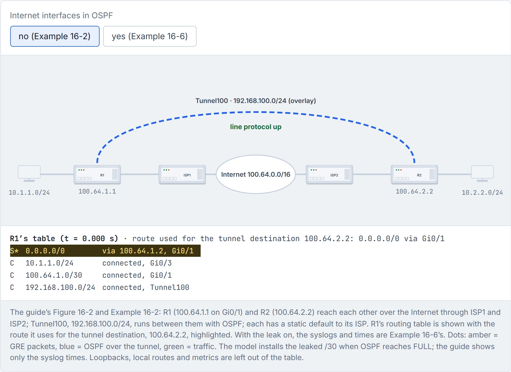
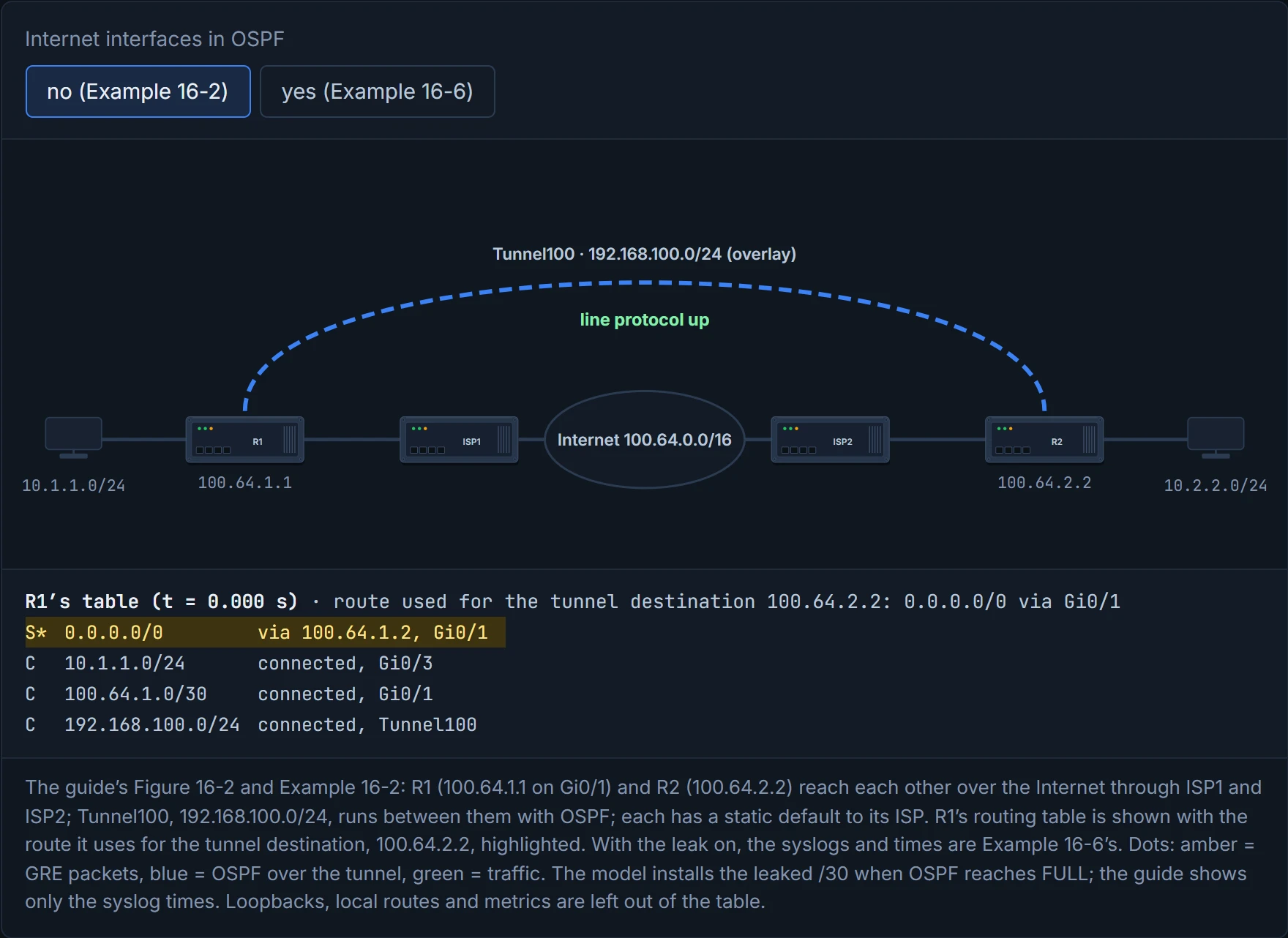
Step 1 of 2 R1 has a route to the tunnel destination, 100.64.2.2: its static default towards ISP1. That’s all GRE needs for the line protocol to come up; the GRE packets travel inside ordinary IP packets across the Internet, protocol 47.
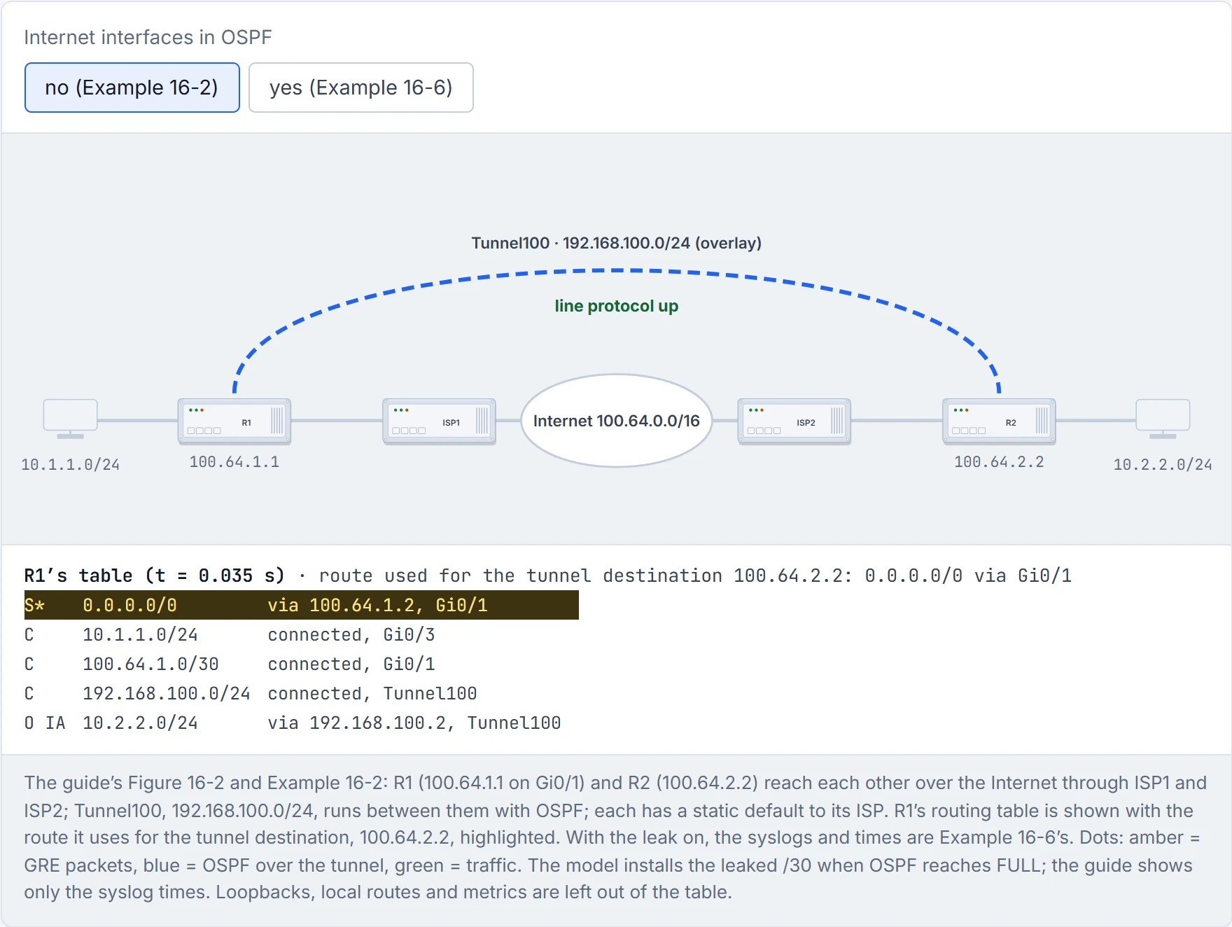
Step 2 of 2 OSPF forms an adjacency over Tunnel100 and R1 learns 10.2.2.0/24 via 192.168.100.2 (Example 16-4). The tunnel destination still resolves through the default and Gi0/1, so the tunnel stays up; traffic from 10.1.1.0/24 to 10.2.2.0/24 crosses in one hop (Example 16-5).
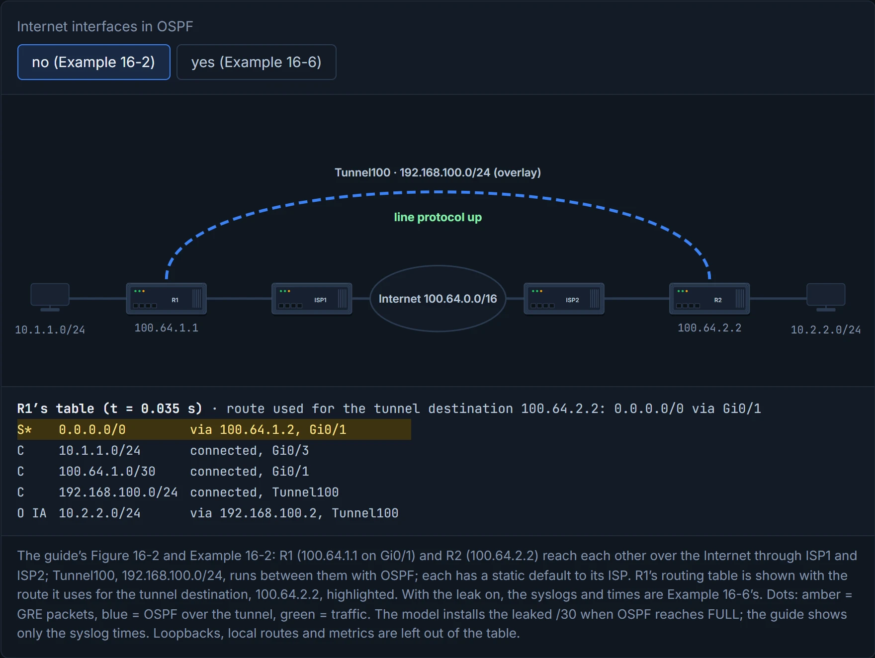
The router doesn't loop forever. It logs "looped chain attempting to stack", then "%TUN-5-RECURDOWN: Tunnel100 temporarily disabled due to recursive routing", the tunnel goes down, OSPF loses its neighbour, the /30 disappears, the default takes over, the tunnel comes back up, and it all happens again: in Example 16-6, 15 seconds up and about 65 seconds down, over and over. Cisco's summary: "The best path to a tunnel destination is via the tunnel itself; therefore recursive routing causes the tunnel interface to flap". Have you ever noticed how a phone that forwards calls to itself rings for a moment, drops, and then tries again? Same shape of fault, and it repeats until someone fixes the forwarding.
The fix is to stop advertising the tunnel endpoints across the tunnel: take the Internet-facing interfaces out of OSPF. That's quiz Q3: the tunnel source interface or address shouldn't be advertised into the tunnel. Cisco's general ways to "keep the control-plane routing separate from the tunnel routing": a different routing process or tag, a different routing protocol, or static routes for the endpoints. A static fix has to beat the learned /30: a more specific route, such as ip route 100.64.2.2 255.255.255.255 100.64.1.2, wins by longest match. Mind quiz Q3's distractors: the tunnel's own overlay address must be advertised (Example 16-2 advertises 192.168.100.1 into area 0), and if you source the tunnel from a loopback, that loopback becomes the address to keep out of the overlay's routing protocol. (The guide also names outbound interface selection as a second overlay problem, without developing it.) The memory hook: reach the endpoint through the underlay, the LANs through the tunnel; never the endpoint through the tunnel.
Recursive routing is a tunnel trying to dig itself.
Continue the lesson
The whole lesson, with its drawings and its questions. The rest of this section and 9 more after it.