
Routing inside VRFs: EIGRP, OSPF and BGP VRF-Lite
Static routes in a VRF stop scaling once a customer adds sites. Run a routing protocol per VRF instead. EIGRP uses named mode, with an address family for each VRF. OSPFv2 runs a separate process per VRF, such as router ospf 1 vrf BLUE. Verify each with vrf in the show command, as in show ip eigrp vrf RED interfaces.
By Arif, founder of Daveth · Updated
The full 12 min walkthrough is in Daveth Pro (Network). See what the plan opens
What this page answers
How do you configure EIGRP for a VRF?
In EIGRP named mode: router eigrp name, then address-family ipv4 vrf vrf-name autonomous-system as-number for each VRF, with its network statements inside. Read it in “EIGRP: one process, one family per VRF”
How do you configure OSPF for a VRF?
With a separate process per VRF, such as router ospf 1 vrf BLUE and router ospf 2 vrf GREEN, and each VRF's interfaces placed in its own process. Read it in “OSPF: a process per VRF, or a family per VRF”
Four statics, and then a second site
The last lesson left PARTNER running on four static routes: one per router, per family, across one cable. It worked. Now the partner wants a second user LAN behind R-ABR1, and next quarter a third. Each new network is another static on every router that carries PARTNER, in both families, typed by hand and never withdrawn when a link dies. The choice is the usual one: for all the routers to learn about all the other networks you can use static or dynamic routing. This lesson goes on with EIGRP, and you could use any other dynamic routing protocol, such as OSPF or BGP.
So: does every routing protocol need its own copy per VRF?
Something of its own for each VRF, always. Whatever learns PARTNER's routes has to talk only to PARTNER's neighbors, on PARTNER's interfaces, and write only into PARTNER's table, or the last lesson's wall has a hole in it. Whether that takes a second running copy of the whole protocol is where the four differ. One of them starts a different process for each VRF. The other three open an address family for the VRF inside a process that runs once. Put the same three questions to each of them:
- Where do you name the VRF?
- What do you keep once per VRF?
- How do I ask you about one VRF, and only that one?
One thing about the third question before the first protocol answers it. A protocol's own per-VRF views are given in this lesson for EIGRP and for OSPFv3 only. For OSPFv2 and BGP the answer is two commands that ask about a VRF whatever the protocol: show ip protocols vrf NAME, which displays the routing protocol information associated with a VRF, and show ip route vrf NAME with the protocol after the name. The four-way comparison near the end says what each of the two proves.
EIGRP goes first and takes its time, on a full worked example with its output. OSPF gets a paragraph and one configuration, BGP a configuration and a surprise.
Everything from the last lesson is assumed, in one line: the VRFs exist (vrf definition), each interface is in exactly one (vrf forwarding), each table is read with show ip route vrf NAME, and a test from the router names the VRF (ping vrf NAME). The lab is the last lesson's too: R1, R2 and R3 in a row, RED on 10.0.0.0/8, GREEN on 172.16.0.0/16 and BLUE on 192.168.0.0/16, three PCs behind R1 and three behind R3, and each router-to-router cable carrying all three VRFs as tagged subinterfaces. At this point every VRF table holds only its own connected and local routes.
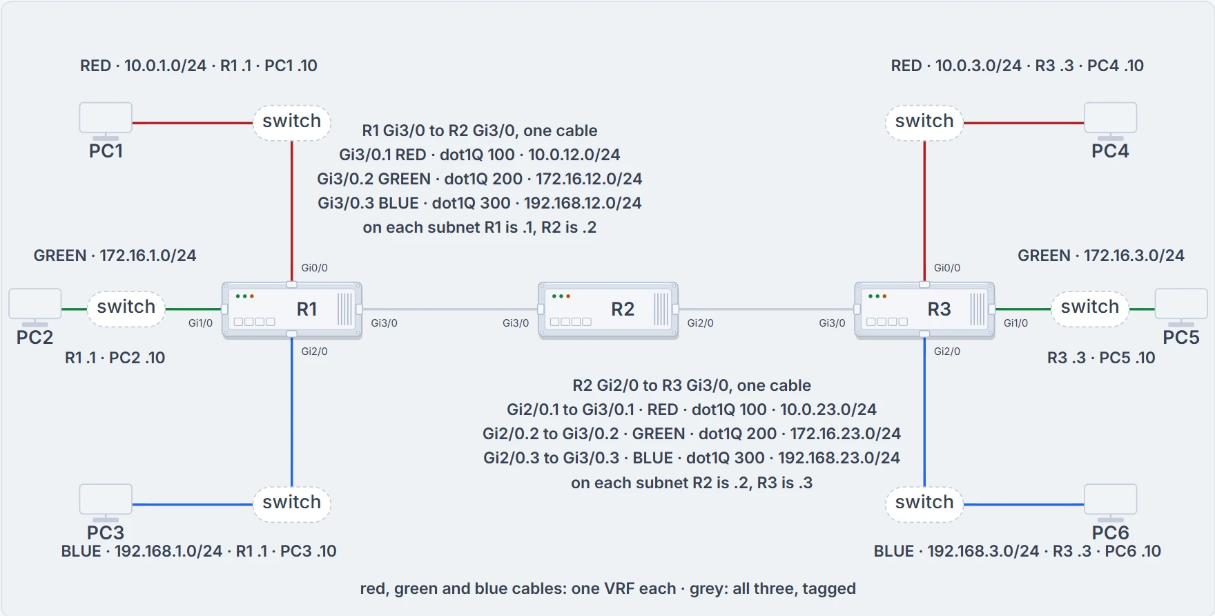
Three VRFs on three routers: which interfaces could each VRF's routing protocol ever use? Follow one colour across the row. Each cable between routers carries all three VRFs as tagged subinterfaces. PC1 to PC3's .10 addresses are ours. R1 also has IPv6 addresses on these six interfaces; they're left off because nothing in this lesson routes them.
Look at R1's RED table before you go on:
R1# show ip route vrf RED
Routing Table: RED
...output omitted...
Gateway of last resort is not set
      10.0.0.0/8 is variably subnetted, 4 subnets, 2 masks
C        10.0.1.0/24 is directly connected, GigabitEthernet0/0
L        10.0.1.1/32 is directly connected, GigabitEthernet0/0
C        10.0.12.0/24 is directly connected, GigabitEthernet3/0.1
L        10.0.12.1/32 is directly connected, GigabitEthernet3/0.1
10.0.1.0/24 on Gi0/0 and 10.0.12.0/24 on Gi3/0.1, and nothing about R3's 10.0.3.0/24. The output proves what is installed in RED's table; it can't say why a route is missing. Two sections from now the table will have R3's LAN, and GREEN's and BLUE's tables won't.
EIGRP: one process, one family per VRF
To configure EIGRP for several VRF instances you use EIGRP named configuration mode, because it permits you to create multiple address families. You enter it with router eigrp name in global configuration mode, then create an address family for each VRF with address-family ipv4 vrf vrf-name autonomous-system as-number, and then give that family whatever EIGRP commands the scenario needs; here, enabling the routing process on only certain interfaces. On R1:
R1(config)# router eigrp VRFEXAMPLE
R1(config-router)# address-family ipv4 vrf RED autonomous-system 10
R1(config-router-af)# network 10.0.1.1 0.0.0.0
R1(config-router-af)# network 10.0.12.1 0.0.0.0
R1(config-router)# address-family ipv4 vrf GREEN autonomous-system 172
R1(config-router-af)# network 172.16.1.1 0.0.0.0
R1(config-router-af)# network 172.16.12.1 0.0.0.0
R1(config-router)# address-family ipv4 vrf BLUE autonomous-system 192
R1(config-router-af)# network 192.168.1.1 0.0.0.0
R1(config-router-af)# network 192.168.12.1 0.0.0.0
R1(config-router-af)# end
No exit is typed between the families: each new address-family line follows straight on from the previous family's last network line.
That's the first question answered. EIGRP names the VRF on the address-family line, and the EIGRP lessons already told you what else lives on that line: the AS. VRFEXAMPLE is the name that router eigrp name asks for, and even a number typed there doesn't correlate to the autonomous system number. RED's autonomous system is 10, GREEN's 172, BLUE's 192. One process, three families, three autonomous systems. That's most of the second answer as well. What EIGRP keeps once per VRF is the whole family, and there's a word for a family: named mode makes it possible to run multiple instances under the same EIGRP process. The next section shows each one holding its own interfaces, neighbors and routes. The old rule still holds inside each: routers exchange routes only with members of the same autonomous system, so R2's RED family has to say 10 as well.
Do the three numbers have to differ? Not as this lesson works it: each VRF simply got a number of its own. In the figure below, three families that all say AS 10 are drawn as three separate instances.
And classic mode? It can do VRFs too. There, an EIGRP process running in a VRF needs its autonomous-system number entered with the autonomous-system command in address-family configuration mode, and that extra line is the one people forget. Named mode carries the number on the address-family line itself, and it's the form this lesson uses from here on.
Now the line that causes trouble later. Look at the prompt on every network line: R1(config-router-af)#. It's the same prompt in RED's family, in GREEN's and in BLUE's. Nothing on the line you're typing says which family you're in.
And it matters, because of what a network statement is. From the first EIGRP lesson: it doesn't advertise a network, it selects interfaces by address, and EIGRP then adds each selected interface's connected network. What does it select from, inside a VRF family? The output the next section reads shows the pattern: each EIGRP AS contains only the interfaces that have been enabled for the EIGRP routing process in the respective VRF.
So here is this lesson's working rule: a statement under a VRF's family selects only from that VRF's interfaces. A statement is two things, then: the family it's typed under, and the address in it. Same number, different table. The last lesson said that of an interface address, and it's just as true of the address in a network statement.
One line from the last lesson before the question, because the answer needs it: a packet is looked up in the table of the VRF it arrived in, and a router with no route for it there answers the sender with an unreachable from its own address on that interface.
Predict one before you touch the figure. Someone builds R1's configuration from the listing above with one line in the wrong place: network 10.0.1.1 0.0.0.0 sits under GREEN's family, between GREEN's own two statements, and is no longer under RED's. Moved, not copied.
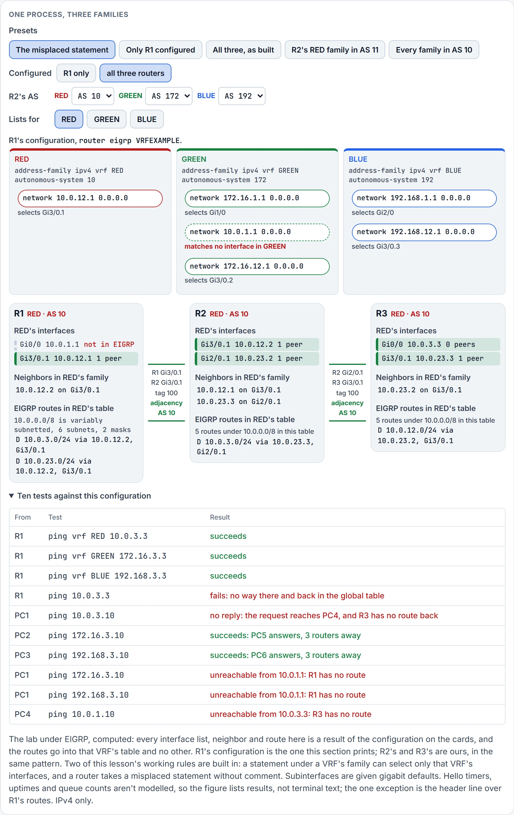
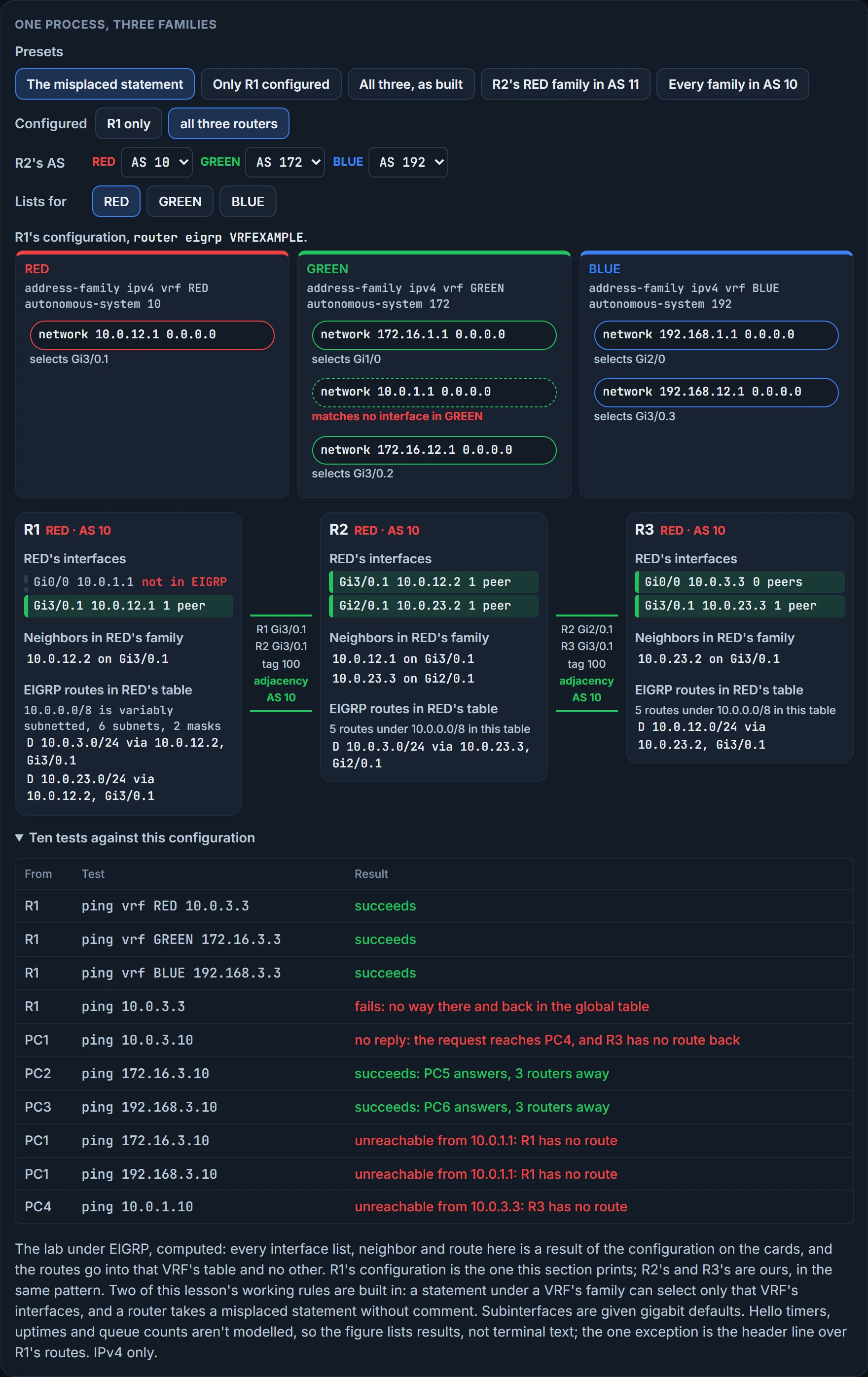
GREEN gains nothing and still runs on Gi1/0 and Gi3/0.2; RED loses Gi0/0 and runs on Gi3/0.1 alone. Now notice how quiet that is. R1's RED neighbor stays up, GREEN is untouched, and nothing on R1 looks broken. The first to notice is at the far end, where PC4 is refused from 10.0.3.3, R3's own RED address on PC4's LAN. A line that exists, in a family that can't use it.
IPv6 follows the EIGRP lessons too. The named-mode step is address-family {IPv4 | IPv6} {unicast | vrf vrf-name} autonomous-system as-number, so RED's IPv6 family is address-family ipv6 vrf RED autonomous-system 10. And a named IPv6 family has no network statements at all: when it's configured, all the IPv6-enabled interfaces immediately start participating. Inside a VRF, that's all the IPv6-enabled interfaces in that VRF. Keep the difference in mind: IPv4 joins by statement, IPv6 joins by being there.
Not confirmed on a router, for this section: that a statement under a VRF's family can select only that VRF's interfaces; what happens when one address exists in two tables; what a router says, if anything, to a statement that matches no interface in its family; whether three families may share one AS number; and what an IPv6 family in a VRF takes and prints. The lab's own outputs are IPv4 only.
Asking EIGRP about one VRF
Third question: how do you ask EIGRP about RED and only RED? You put vrf RED in the show command. To verify that the interfaces are participating in the EIGRP process for the correct VRF, use show ip eigrp vrf vrf-name interfaces. RED's, on R1:
R1# show ip eigrp vrf RED interfaces
EIGRP-IPv4 VR(VRFEXAMPLE) Address-Family Interfaces for AS(10)
           VRF(RED)
                   Xmit Queue   PeerQ        Mean   Pacing Time   Multicast    Pending
Interface   Peers  Un/Reliable  Un/Reliable  SRTT   Un/Reliable   Flow Timer   Routes
Gi0/0       0      0/0          0/0          0      0/0           0            0
Gi3/0.1     0      0/0          0/0          0      0/0           0            0
Read the two header lines before the table: VR(VRFEXAMPLE) is the named process, AS(10) the family's autonomous system, VRF(RED) the VRF: the output tells you which instance answered. Then the rows: Gi0/0 and Gi3/0.1, RED's two interfaces. GREEN's output says AS(172), VRF(GREEN), and lists Gi1/0 and Gi3/0.2; BLUE's says AS(192), VRF(BLUE), with Gi2/0 and Gi3/0.3. The columns are the ones the first EIGRP lesson read. Peers is 0 on every row, and that's right: at this moment only R1 is configured.
What does it prove? That these interfaces run EIGRP in this VRF's family. It doesn't prove a neighbor is there, and it says nothing about any other VRF, or about the global table.
When all the other routers have been configured for EIGRP, you verify neighbor adjacencies with show ip eigrp vrf vrf-name neighbors, and because you're dealing with several VRF instances, each show command displays only the neighbors that are within that VRF instance. RED's:
R1# show ip eigrp vrf RED neighbors
EIGRP-IPv4 VR(VRFEXAMPLE) Address-Family Neighbors for AS(10)
           VRF(RED)
H   Address         Interface        Hold Uptime   SRTT   RTO  Q  Seq
                                     (sec)         (ms)       Cnt Num
0   10.0.12.2       Gi3/0.1            13 00:02:31   48   288  0  7
One neighbor, R2's RED address, on RED's subinterface. GREEN's neighbor is 172.16.12.2 on Gi3/0.2 and BLUE's is 192.168.12.2 on Gi3/0.3. The rest of their rows: GREEN's has hold 12 and uptime 00:02:09, then SRTT 64, RTO 384, Q count 0 and sequence number 7; BLUE's has hold 12 and uptime 00:01:53, then 49, 294, 0 and 7. Count the routers: R1 has exactly one physical neighbor, R2, and three EIGRP adjacencies with it, one per VRF, each over its own subinterface. Three conversations on one cable, and each show command lists only its own.
A neighbor here proves two families agreed across one link: same subnet, same AS, the neighbor lesson's conditions. It doesn't prove any route arrived. And notice what made R1's RED talk to R2's RED. Not the name. VRF instances are locally significant, and consistent naming is asked for only to simplify operations; the adjacency formed because both ends of tag 100 sit in a family with AS 10. If R2's RED family said AS 11, R1's RED would list Gi0/0 and Gi3/0.1 with no peers and no EIGRP routes, while GREEN and BLUE carried on untouched.
An empty answer to the wrong question.
Once each VRF network converges, you check that the routing tables hold the EIGRP-learned routes with show ip route vrf vrf-name; adding eigrp limits the output to just the EIGRP-learned routes. Before the output, a prediction. Only the order: the numbers, and the formula behind them, come after it.
R1# show ip route vrf RED eigrp
Routing Table: RED
...output omitted...
Gateway of last resort is not set
      10.0.0.0/8 is variably subnetted, 6 subnets, 2 masks
D        10.0.3.0/24 [90/20480] via 10.0.12.2, 00:02:17, GigabitEthernet3/0.1
D        10.0.23.0/24 [90/15360] via 10.0.12.2, 00:03:51, GigabitEthernet3/0.1
Both routes are D with distance 90, both point at 10.0.12.2 out of Gi3/0.1, and the header says six subnets: R1's own four from before plus these two. The numbers are the metrics lesson's wide formula, because named mode uses wide metrics: 65,536 × (10^7 / minimum bandwidth + latency / 10^6), divided by the rib-scale of 128 that named mode prints. A gigabit link's 10 microseconds is 10 after the conversion. To 10.0.23.0/24 the path crosses two gigabit interfaces: 65,536 × (10 + 20) = 1,966,080, and 1,966,080 / 128 is 15360. To 10.0.3.0/24 it crosses three: 65,536 × (10 + 30) = 2,621,440, over 128, 20480. One more hop, 5120 more. The figure in the last section lists its routes with these numbers from now on.
GREEN's table gains 172.16.3.0/24 at [90/20480] and 172.16.23.0/24 at [90/15360], both via 172.16.12.2 on Gi3/0.2, under 172.16.0.0/16 is variably subnetted, 6 subnets, 2 masks. BLUE's gains 192.168.3.0/24 and 192.168.23.0/24 with the same two metrics via 192.168.12.2 on Gi3/0.3, and no header line at all: each is a whole class C network on its own, which is the last lesson's header rule again. Same shape, three times, and no prefix of one VRF in another's table.
show ip route vrf RED eigrp proves the route won its place in RED's table. It doesn't prove the return path, and it doesn't prove a host can use it. For that, ping: ping vrf vrf-name ipv4-address from R1 to R3's LAN address in each VRF, 10.0.3.3, 172.16.3.3 and 192.168.3.3, all three 100 percent. ping 10.0.3.3 without vrf still fails: nobody gave the global table anything. A router's ping vrf proves this router, this table, there and back. It doesn't prove a host's path, because a host's packets arrive on another interface.
And then the PCs: five pings typed at PC prompts (the prompts read PC-1, PC-2 and PC-3), and the point of them is that communication is isolated to the VRF instance. PC1 pings PC4 at 10.0.3.10, both in RED, and it succeeds; PC2 to PC5 at 172.16.3.10 in GREEN and PC3 to PC6 at 192.168.3.10 in BLUE succeed too. PC1 to PC5 and PC1 to PC6, those same two addresses tried from a RED host, fail, because they're in different VRF instances. The successes print ttl=61; the failures come from 10.0.1.1, PC1's own gateway, as ICMP type 3, code 1, destination host unreachable. R1 looked up GREEN's address in RED's table and found nothing, and the unreachable is R1 saying so. EIGRP filled three tables and built no way between them.
Not confirmed on a router, for this section: what plain show ip eigrp neighbors prints on a router that has only VRF families; how we read the two header lines; and that a subinterface takes its parent's gigabit defaults, which is what makes these two metrics come out.
OSPF: a process per VRF, or a family per VRF
Same three questions, faster. OSPFv2 first. If you were to use OSPFv2 for routing, you could create different processes, for example router ospf 1 vrf BLUE, router ospf 2 vrf GREEN and router ospf 3 vrf RED, and then configure the respective interfaces in the correct OSPFv2 process. The command is router ospf process-id [vrf vrf-name], and each VRF is given a process number of its own.
So OSPFv2 names the VRF on the process line, and its per-VRF copy is a whole process. That's the heaviest spelling of the four, and RFC 4364 says it of providers in the same breath: a PE that is an OSPF peer of CE routers in distinct VPNs must be running multiple instances of OSPF (its section 7; a PE is a provider's edge router and a CE a customer's, and the MPLS lessons live on those two words). The first OSPF lesson already had the reason a process works as a wall: each OSPF process maintains its own unique database, and routes learned in one process are not available to a different process without redistribution. The numbers 1, 2 and 3 are only a choice. OSPF process numbers are locally significant, so R2 could call RED's process anything. This lesson's working rule is that one process serves one table: one VRF, or the global table, never two. For placing the interfaces, the first OSPF lesson's two ways are the candidates, a network statement under the process or ip ospf on the interface, and the working rule is the scope EIGRP's families showed: a VRF's process accepts only that VRF's interfaces. To ask about one VRF, use the two commands from the start of this lesson. show ip protocols vrf RED proves OSPF is configured for RED, and it doesn't prove a neighbor or a route. show ip route vrf RED ospf proves which OSPF routes are installed in RED's table, and not which neighbor or process should have supplied a missing one.
OSPFv3 spells it the way EIGRP did. If you were using OSPFv3 address families, you could create a different address family for each VRF instance and then configure the respective interfaces to participate in the OSPFv3 process:
R1(config)# router ospfv3 1
R1(config-router)# address-family ipv4 vrf RED
R1(config-router-af)# exit
R1(config-router)# address-family ipv4 vrf GREEN
R1(config-router-af)# exit
R1(config-router)# address-family ipv4 vrf BLUE
R1(config-router-af)# exit
R1(config-router)# interface gigabitethernet 0/0
R1(config-if)# vrf forwarding RED
R1(config-if)# ip address 10.0.0.1 255.255.255.0
R1(config-if)# ipv6 enable
R1(config-if)# ospfv3 1 ipv4 area 0
One process, three families. (This listing uses 10.0.0.1 for Gi0/0.) Now the interface line: ospfv3 1 ipv4 area 0 names a process, a family type and an area. It doesn't name a VRF.
RED's. The interface is configured for the RED VRF instance, so the ospfv3 process-id ipv4 area area-id command automatically places it in the RED OSPFv3 address family. The result shows in show ospfv3 vrf RED interface brief:
R1# show ospfv3 vrf RED interface brief
Interface    PID   Area            AF         Cost  State
Gi0/0        1     0               ipv4       1     DR
Process 1, area 0, family ipv4, cost 1, state DR. The row goes on with one more column, which this lesson doesn't use. A gigabit interface at cost 1 and a router alone on its segment calling itself DR are the OSPF lessons', nothing new. The row proves Gi0/0 is in RED's family of process 1. It doesn't prove an adjacency or a route, or anything beyond R1.
Two things on that interface aren't about VRFs at all. ipv6 enable is there because OSPFv3 exchanges its packets over IPv6 link-local addresses even when the family is IPv4: OSPFv3 requires an IPv6 link-local address to form the adjacency, as the OSPFv3 lesson taught. So an IPv4-only interface in a VRF still needs it. And the family line reads address-family ipv4 vrf RED, with no unicast, where the OSPFv3 lesson's families were address-family ipv4 unicast. An IPv6 family for a VRF would be address-family ipv6 vrf RED, with ospfv3 1 ipv6 area 0 on the interface, by the same pattern.
Not confirmed on a router, for this section: whether a router refuses one OSPFv2 process number for two VRFs, and in what words; how a VRF's interfaces are placed in its OSPFv2 process, and OSPFv2's own per-VRF show commands; whether the VRF's own definition also needs address-family ipv6 before ipv6 enable does its job; the family line with or without unicast; and the IPv6 forms, which follow the pattern and aren't shown with output.
Continue the lesson
The whole lesson, with its drawings and its questions. 3 more sections after the ones above.