
VRF-Lite: one router, several routing tables
Every router already has one routing table, the global one; VRF-Lite adds more, so one router can keep several networks from ever seeing each other. Create a VRF with the classic IPv4-only commands or the newer set for IPv4 and IPv6, then put interfaces in it with vrf forwarding. A packet is looked up in the table of the VRF its interface belongs to.
By Arif, founder of Daveth · Updated
The full 12 min walkthrough is in Daveth Pro (Network). See what the plan opens
What this page answers
How do you configure VRF-Lite?
Create the VRF, with vrf definition and its address families or the classic ip vrf, then put each interface in it with vrf forwarding, or ip vrf forwarding in the classic set, and re-enter its addresses. Read it in “Putting interfaces behind the wall”
Why does show ip route show no routes after configuring VRFs?
Because the interfaces are now in VRFs, and show ip route reads only the global table. Their routes are in each VRF's own table: show ip route vrf name. Read it in “Where the routes went”
Your routing table was never the only one
Can one router keep three networks from ever seeing each other? Yes. The interesting part is proving it, and that starts with something you've never had to think about.
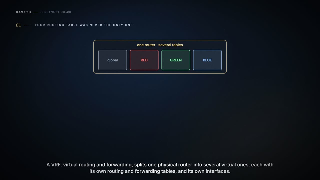
Every show ip route you've run in this course read one table, and that table has an owner. Out of the box, every interface a router has, its routing table and its forwarding tables all sit in a single instance, the global VRF. So "your routing table" has always been the global VRF's routing table. VRF stands for virtual routing and forwarding, and it does what the name says: it makes separate virtual routers inside one physical router. Each VRF instance you add is one more virtual router, with a routing table and a forwarding table of its own. An interface, a routing table and a forwarding table each belong to one instance and are walled off from the others, and that wall is why traffic in one VRF can't get in the way of traffic in another.
VRF-Lite is VRF without MPLS. The full version is an essential piece of the MPLS Layer 3 VPN design, and the MPLS lessons bring that half; nothing in this lesson carries a label. What VRF buys you either way is segmentation: one router doing a job you'd otherwise need several devices for. If an exam asks for the two terms, VRF is router virtualization, several routing tables on one router, each isolated from the others, and VRF-Lite uses VRF to build several routing domains across the same routers.
Why bother? One possible reason is security. Say three networks must never see each other's traffic, and you only want to build one physical network to carry them. This lesson's lab is that network: R1, R2 and R3 in a row, three PCs on R1 and three on R3, and three logically isolated networks on the same routers and cables, RED using 10.0.0.0/8, GREEN using 172.16.0.0/16 and BLUE using 192.168.0.0/16. VRF-Lite keeps each network's traffic to itself by giving every router one virtual routing table per VRF. Here it is, with every address this lesson uses.
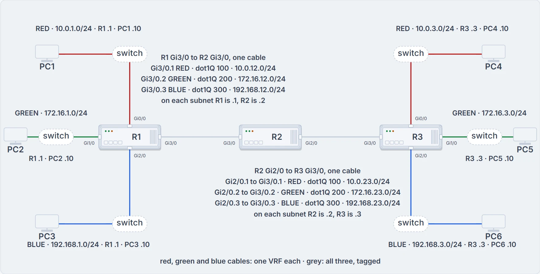
The lab: three networks on three routers, and each cable between routers carries all three. PC1 to PC3's .10 addresses are ours; the switches do nothing else in this lesson.
Look at the links between the routers. R1 meets R2 on one physical interface, Gi3/0, and R2 meets R3 on one more, and each of those cables carries all three networks: R1's Gi3/0 is split three ways, .1, .2 and .3. Three networks, one cable each way. How that works is two sections on.
You've already met one consequence. The EIGRP lesson showed named mode giving each VRF its own address family, with every check naming the VRF; running routing protocols inside VRFs is the next lesson's. This lesson builds the VRFs, puts interfaces in them, routes statically inside them, and proves the walls hold.
Two ways to make a table
IOS gives you two command sets for this. The classic set supports only IPv4 addressing and networks; the newer set supports both IPv4 and IPv6. The exam could test you on either, so this lesson teaches both. A command that isn't marked as classic or new works with both: show ip route vrf is one.
Creating a VRF is one line in either set: ip vrf RED in the classic one, vrf definition RED in the new one, and the same again for GREEN and BLUE. The new one has a second step. Anything you configure at the root of a vrf definition applies to IPv4 and IPv6 alike, but you still have to enable the VRF for each family with address-family [ipv4 | ipv6] [unicast | multicast], and any command you enter in address family mode affects only that family. R1 gets both families on every VRF; ? after address-family offers exactly two, ipv4 and ipv6:
R1(config)# vrf definition RED
R1(config-vrf)# address-family ipv4 unicast
R1(config-vrf-af)# exit
R1(config-vrf)# address-family ipv6 unicast
R1(config-vrf-af)# exit
R1(config-vrf)# exit
The help in VRF mode shows what else lives there: address-family, default, description, exit, help, ipv4, no, rd, route-target, vnet and vpn. Two of those you'll hear about soon. A route distinguisher isn't a requirement for VRF-Lite except when MP-BGP is used, and route targets aren't a requirement either; the next lesson and the MPLS lessons take both.
Check what you built. The classic command is show ip vrf, the new one show vrf. Both list each VRF with its default RD, <not set> for BLUE, GREEN and RED. The Interfaces column is empty: no interface is in any of them yet, and until one is, nothing is separated. show vrf adds a Protocols column, the families taking part in each VRF.
IPv4 only. A family missing from the Protocols column means nobody used address-family to enable it in the VRF's definition. IPv6 isn't switched on in PARTNER, so an IPv6 address on a PARTNER interface has no PARTNER table to go into. show vrf proves which VRFs exist and which families each one has. It doesn't prove any interface is in them, or that any route is.
One more rule, and it bites. VRF names are case sensitive: red isn't RED, or Red, or rED. Here's the fault it produces. Someone types vrf definition Green between RED and BLUE, and every interface line after it says vrf forwarding GREEN. That router has a VRF called Green and none called GREEN, so the interface lines name a VRF that doesn't exist, and show vrf is where you'd see it, with Green in the list where GREEN should be. The keyword is another matter: type show ip route VRF BLUE and you still get BLUE's table, so the keyword vrf doesn't care about case and the name after it does. And one router's VRF names mean nothing to the next router: VRF names are locally significant, but naming them consistently on every router is what keeps operations simple. Consistently includes case.
Not confirmed on a router, for this section: whether a classic ip vrf is accepted with no rd line under it, what a router does with an IPv6 address on an interface whose VRF has only IPv4 enabled, and the message it prints when vrf forwarding names a VRF that doesn't exist.
Putting interfaces behind the wall
An interface joins a VRF with the classic ip vrf forwarding vrf-name or the new vrf forwarding vrf-name, in interface configuration mode. On R1, Gi0/0 goes in RED, Gi1/0 in GREEN and Gi2/0 in BLUE, and show ip vrf or show vrf run again shows each interface against its VRF.
The order you do it in matters. Add an interface to a VRF when it already has an IPv4 or IPv6 address, and you get a message of this shape, carrying whichever interface and VRF you typed: % Interface GigabitEthernet0/0 IPv4 disabled and address(es) removed due to enabling VRF GREEN, and the same line for IPv6. The address isn't moved with the interface. It's removed, because the address the interface had doesn't belong to the VRF it's now in. So put the interface in the VRF first and then configure its IPv4 and IPv6 addresses; do it the other way round and you'll be typing the addresses twice. The DMVPN lessons meet the same rule on a spoke: if an IP address is already configured when the VRF is linked to the interface, the address is removed. An interface's address doesn't follow it into a VRF.
Now the cable from the drawing. Each interface can belong to only a single VRF. So when one physical interface has to carry several VRFs, you break it into subinterfaces, one per VRF. On R1 that's Gi3/0.1 in RED, Gi3/0.2 in GREEN and Gi3/0.3 in BLUE, and show ip vrf lists each VRF with its physical interface and its subinterface. A subinterface needs dot1Q encapsulation, or you can't assign it an IP address, and R2's subinterfaces facing R1 have to use the same VLAN numbers.
R1, addressed in both families:
R1(config)# int gig 0/0
R1(config-if)# ip address 10.0.1.1 255.255.255.0
R1(config-if)# ipv6 address fc00::1/64
R1(config-if)# int gig 1/0
R1(config-if)# ip address 172.16.1.1 255.255.255.0
R1(config-if)# ipv6 address fc01::1/64
R1(config-if)# int gig 2/0
R1(config-if)# ip address 192.168.1.1 255.255.255.0
R1(config-if)# ipv6 address fc02::1/64
R1(config-if)# int gig 3/0.1
R1(config-subif)# encapsulation dot1Q 100
R1(config-subif)# ip address 10.0.12.1 255.255.255.0
R1(config-subif)# ipv6 address fc03::1/64
R1(config-subif)# int gig 3/0.2
R1(config-subif)# encapsulation dot1Q 200
R1(config-subif)# ip address 172.16.12.1 255.255.255.0
R1(config-subif)# ipv6 address fc04::1/64
R1(config-subif)# int gig 3/0.3
R1(config-subif)# encapsulation dot1Q 300
R1(config-subif)# ip address 192.168.12.1 255.255.255.0
R1(config-subif)# ipv6 address fc05::1/64
Gi0/0 and Gi3/0.1 are RED's, Gi1/0 and Gi3/0.2 GREEN's, Gi2/0 and Gi3/0.3 BLUE's, and every address went on after the interface was in its VRF.
Read the numbers closely, because only one of them has to match anything at the far end. Gi3/0.1 is tagged 100, Gi3/0.2 is 200 and Gi3/0.3 is 300, and R2 uses the same pairs. The number after the dot is the router's own name for the subinterface; the tag goes on the wire, and the tag is the thing the other end has to agree with. That's how one cable carries three VRFs. A frame arrives on Gi3/0 with a tag, the tag picks the subinterface, and the subinterface's VRF picks the table. The lesson steps through exactly that two sections on.
Now verify. The classic show ip vrf interfaces and the new show vrf ipv4 unicast interfaces show each interface's IPv4 address, its VRF and whether it's up or down, and the new show vrf ipv6 unicast interfaces does the same for IPv6. On R1 the classic view lists the six interfaces grouped by VRF, from Gi2/0 at 192.168.1.1 in BLUE, and the new IPv4 view lists them by interface, from GigabitEthernet0/0 in RED, up, 10.0.1.1. The IPv6 view gives every interface a link-local FE80:: address and its global one, FC00::1 on Gi0/0 through FC05::1 on Gi3/0.3. These prove that each interface is in the VRF you meant, with the address you meant, and up. They don't prove the far end agrees on the tag, and they don't prove a single route beyond the connected ones.
Two sets, two families, three views. The pairs so far, side by side:
| Task | Classic set, IPv4 only | New set, IPv4 and IPv6 |
|---|---|---|
| Create a VRF | ip vrf vrf-name | vrf definition vrf-name, then address-family ipv4 unicast and address-family ipv6 unicast as needed |
| Put an interface in it, before its addresses | ip vrf forwarding vrf-name | vrf forwarding vrf-name |
| Carry several VRFs on one link | subinterfaces, each with encapsulation dot1Q vlan before its address, the same VLAN at both ends | the same |
| See the VRFs and their interfaces | show ip vrf | show vrf, which adds Protocols |
| See interfaces, addresses and state | show ip vrf interfaces | show vrf ipv4 unicast interfaces, show vrf ipv6 unicast interfaces |
Where the routes went
R1 is built. Before you look at a single table:
Nothing:
R1# show ip route
! the code legend is left out here
Gateway of last resort is not set
R1#
There are no routes in the IPv4 global routing table, even though the interfaces have IPv4 addresses: the interfaces are in VRF instances, so their networks are in the VRF-specific tables instead. Each of those virtual networks needs its own routing table to stay isolated, and each VRF's table was created the moment you typed ip vrf, or, in the new set, enabled the family under vrf definition. show ip route shows the IPv4 global routing table and show ipv6 route the IPv6 global one: they prove what the global table holds, and nothing about any VRF. To see a VRF's table, name it: show ip route vrf RED, and for IPv6 show ipv6 route vrf RED.
RED's table on R1:
R1# show ip route vrf RED
Routing Table: RED
! the code legend is left out here
Gateway of last resort is not set
      10.0.0.0/8 is variably subnetted, 4 subnets, 2 masks
C        10.0.1.0/24 is directly connected, GigabitEthernet0/0
L        10.0.1.1/32 is directly connected, GigabitEthernet0/0
C        10.0.12.0/24 is directly connected, GigabitEthernet3/0.1
L        10.0.12.1/32 is directly connected, GigabitEthernet3/0.1
Read the first line. "Routing Table: RED" is how you know which table you're looking at; the global table above has no such line. Then the four routes, Gi0/0's and Gi3/0.1's connected and local routes, and nothing of GREEN's or BLUE's. GREEN's table on R1 has the same shape: 172.16.1.0/24 on Gi1/0 and 172.16.12.0/24 on Gi3/0.2, each with its connected and local route. BLUE's table has its two class C networks, 192.168.1.0/24 and 192.168.12.0/24, each with its connected and local route. show ip route vrf proves what's installed in that one table. It doesn't prove the far end is reachable, and it says nothing about the other tables.
RED has an IPv6 table on R1 as well, because the family is enabled there, and show ipv6 route vrf RED reads it. It holds the same two interfaces and nothing else. As code, prefix and interface: C FC00::/64 Gi0/0; L FC00::1/128 Gi0/0; C FC03::/64 Gi3/0.1; L FC03::1/128 Gi3/0.1.
Now read the headers, because you'll be asked to predict one later. RED's four routes sit under a single line, 10.0.0.0/8 is variably subnetted, 4 subnets, 2 masks, and GREEN's under 172.16.0.0/16 is variably subnetted, 4 subnets, 2 masks: one header each, for the whole classful network. BLUE has two, 192.168.1.0/24 is variably subnetted, 2 subnets, 2 masks and the same line for 192.168.12.0/24: a header per /24. Each 192.168.x.0/24 is a classful network of its own, so each gets its own header; the subnet count is every route under that header, and "2 masks" is the /24 and the /32.
R2 and R3 are finished in IPv4 only, with the new commands, and they have the shape you've just read. R2 gets the three VRFs with address-family ipv4 unicast, then its subinterfaces, Gi3/0.1-.3 toward R1 and Gi2/0.1-.3 toward R3, each with vrf forwarding, encapsulation dot1Q 100, 200 or 300, and its address. Its interface view shows six interfaces in their VRFs, and each table holds its VRF's two subnets, connected and local: 10.0.12.0/24 and 10.0.23.0/24 in RED, 172.16.12.0/24 and 172.16.23.0/24 in GREEN, 192.168.12.0/24 and 192.168.23.0/24 in BLUE, under the same header shapes as R1's. R3 mirrors R1: Gi0/0 in RED at 10.0.3.3, Gi1/0 in GREEN at 172.16.3.3, Gi2/0 in BLUE at 192.168.3.3, and Gi3/0.1-.3 toward R2, with 10.0.3.0/24 and 10.0.23.0/24 in RED's table and their twins in GREEN's and BLUE's.
To add IPv6 on R2 and R3 you need two things: address-family ipv6 unicast under each definition, because a family has to be enabled in the VRF, and then the addresses.
Not confirmed on a router, for this section: how show ipv6 route vrf lays its output out. The contents above are computed from R1's configuration.
One packet, one table
Here's the rule the whole lesson hangs on. The table is chosen before the lookup. When a packet arrives on an interface, its destination is looked up in the VRF that interface belongs to, and the result of that lookup decides where it goes. RFC 4364 writes that for a provider's circuits to its customers (§3.1); applying it to VRF-Lite is our reading. And a packet the router sends itself, a ping, uses the global table unless you say otherwise: to verify connectivity when using VRF instances, you must specify the VRF with the ping command, or the global routing table is used instead.
- Pick the table. For a packet arriving on an interface, that interface's VRF. For the router's own ping, the VRF named after
vrf, or the global table if there's none. - Find the longest match in that table, and only that table (the longest match of the static routing lesson).
- No match: the packet stops at this router. If it arrived from somewhere else, the router tells the sender so, from its own address on the interface the packet came in on.
- A match out of a subinterface: the frame leaves with that subinterface's tag, the far end's subinterface with the same tag takes it, and that subinterface's VRF is the far router's table.
- Repeat until a router owns the destination address in the table it's looking in. The reply makes the same trip back, starting in the table of the interface the request arrived on.
The tables are the ones you just read: connected and local routes only.
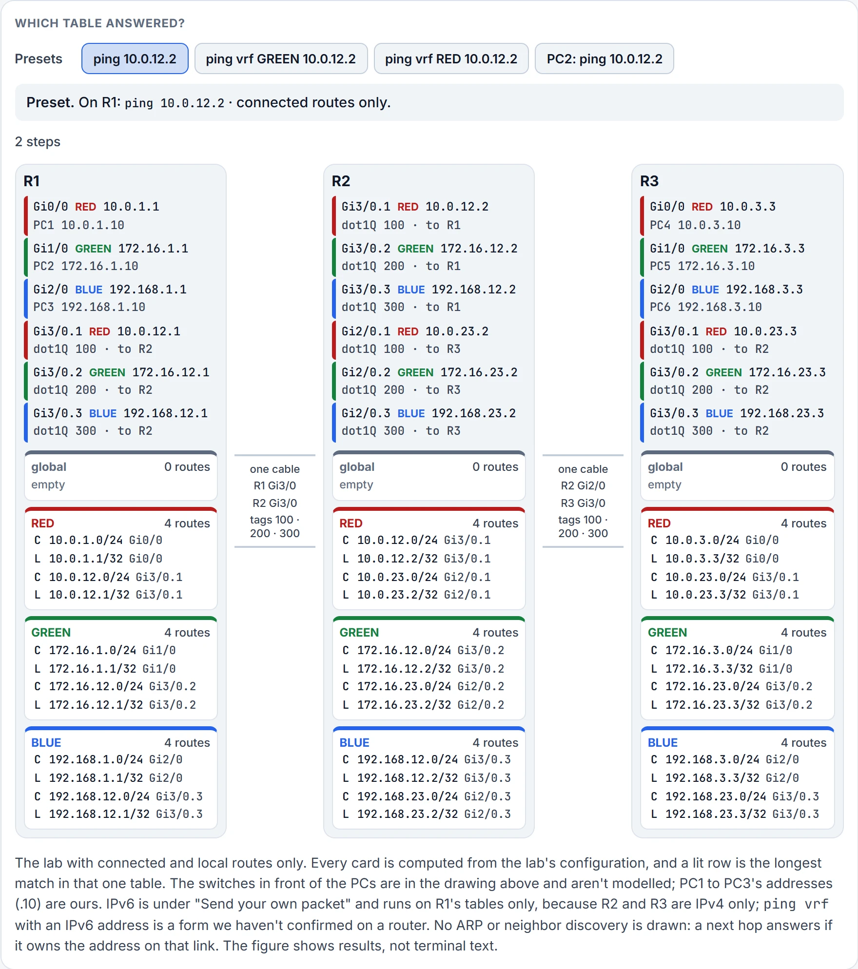
Step 1 of 3 Ready.
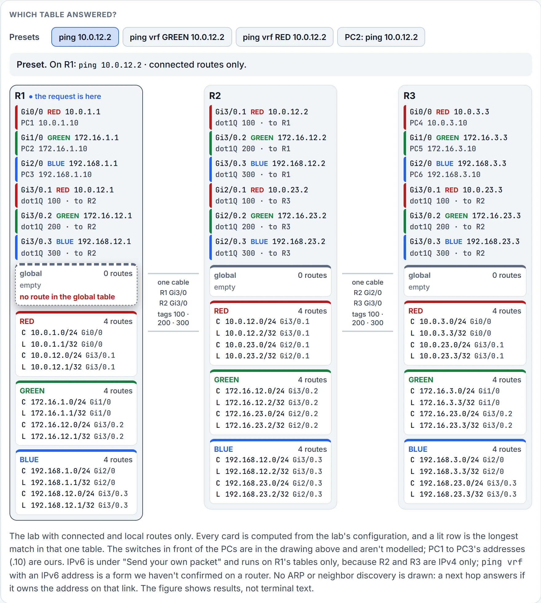
Step 2 of 3 No vrf in the command, so R1 looks in the global table. No route to 10.0.12.2 in the global table, which is empty. Nothing is sent.
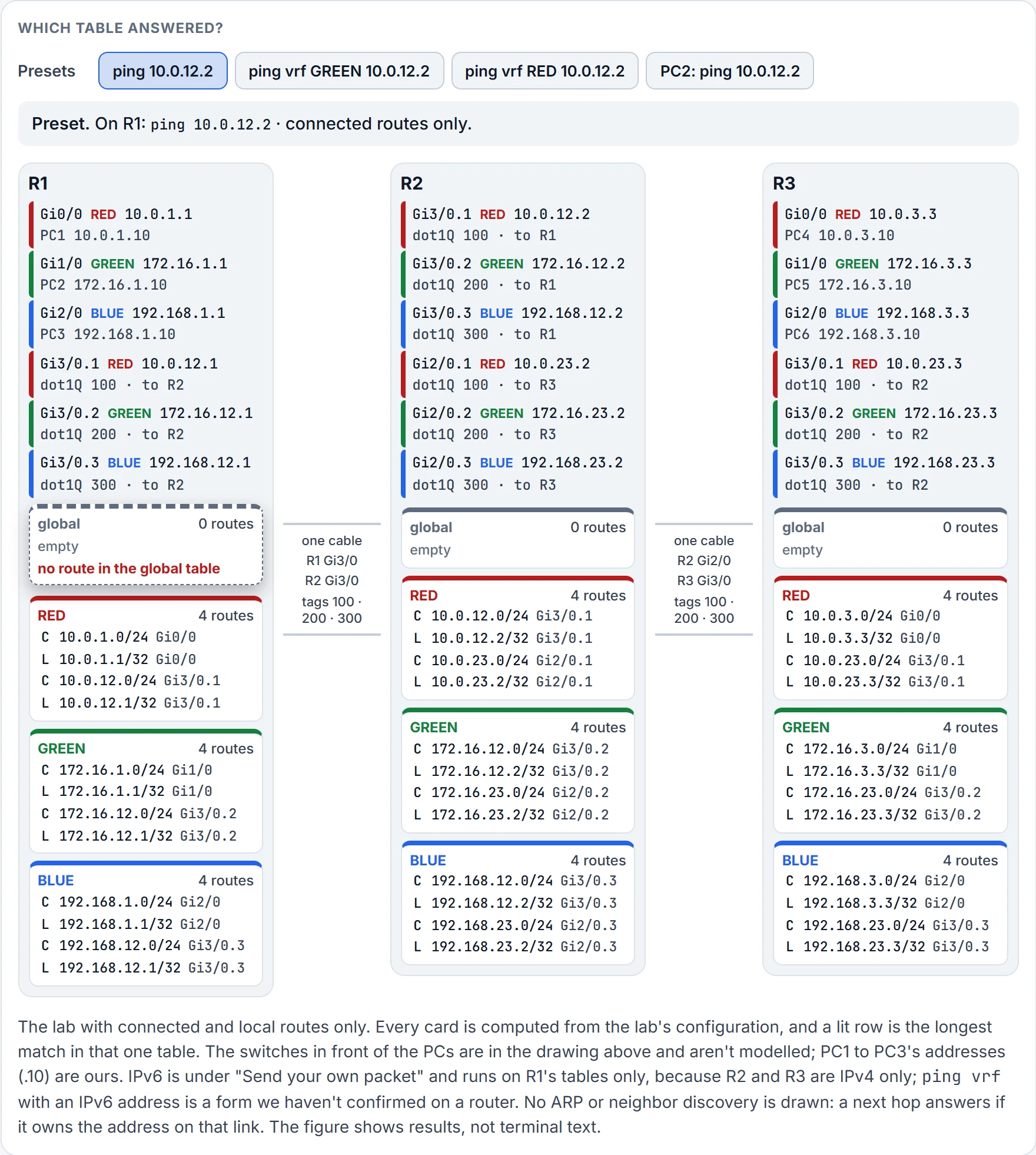
Step 3 of 3 0 percent: no route in the global table on R1.
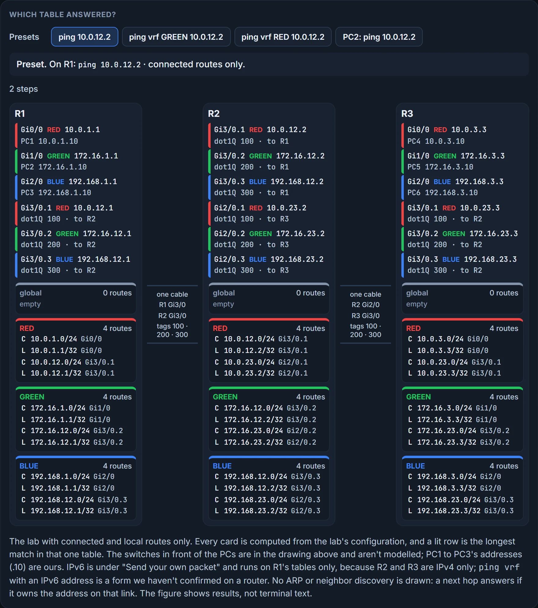
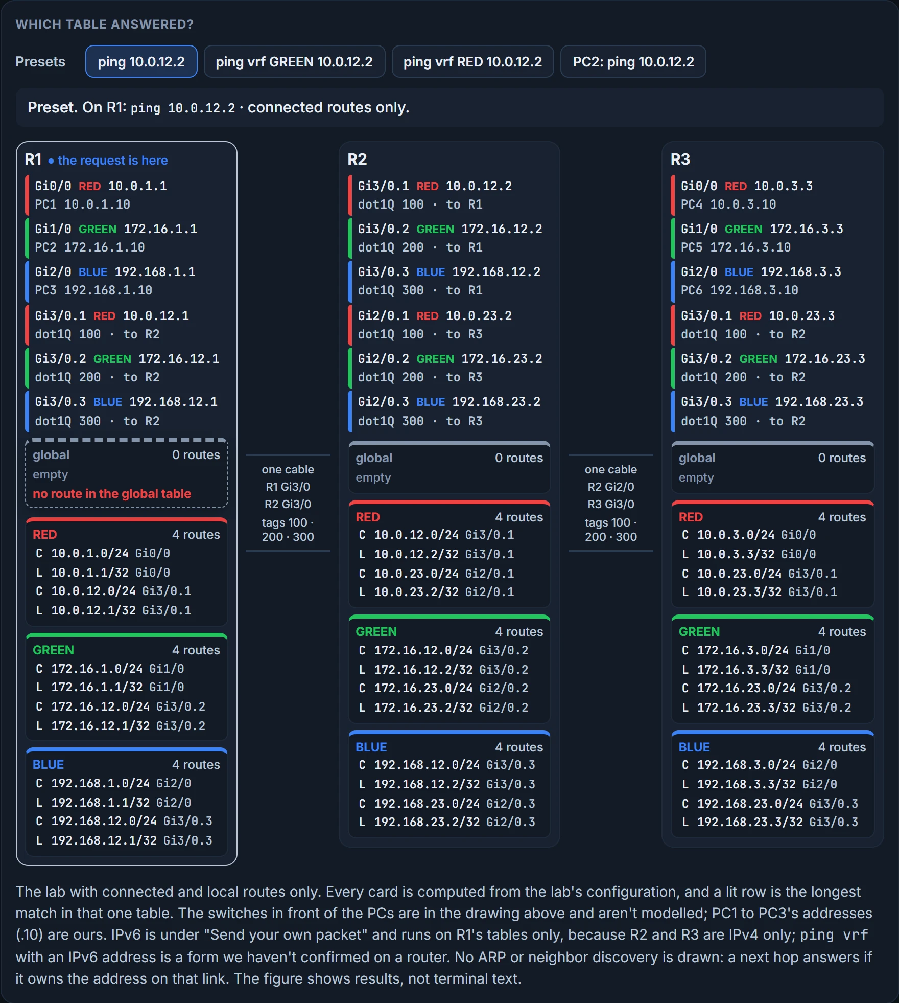
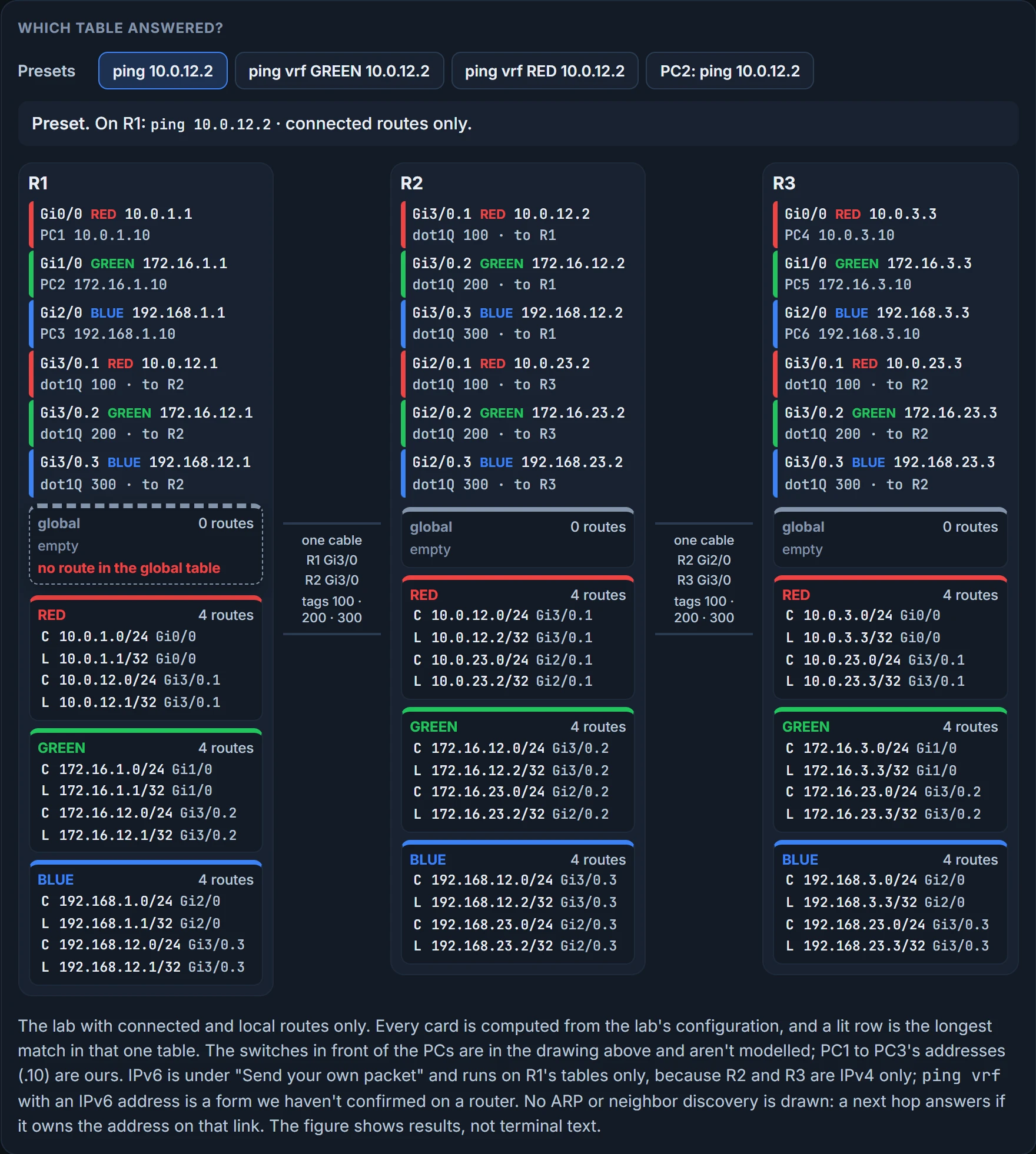
The answers. Only the last ping succeeds. The first fails because the global table is used, and it's empty; the second names GREEN but asks for an address in RED; the third uses the right VRF and an address in it:
R1# ping 10.0.12.2
.....
Success rate is 0 percent (0/5)
R1# ping vrf GREEN 10.0.12.2
.....
Success rate is 0 percent (0/5)
R1# ping vrf RED 10.0.12.2
!!!!!
Success rate is 100 percent (5/5), round-trip min/avg/max = 44/49/60 ms
! two lines of each ping are left out
That's VRF isolation at work, and as clean an example of it as you'll get: the same address, typed three times, and the table decided the answer every time.
And PC2 is answered by R1. PC2's packet arrives on Gi1/0, so R1 looks up 10.0.12.2 in GREEN, finds no route, and answers PC2 with an unreachable from 172.16.1.1, its own GREEN address on that interface. When the unreachable comes from the first router, the lookup failed right there, in that router's table for that interface.
Traceroute takes vrf the same way: traceroute vrf RED 10.0.3.3. A trace in a VRF proves the hops that VRF's packets take from this router. It doesn't prove the path back, or what a host's packets do. Every IOS traceroute this course has shown opens with a legend line, VRF info: (vrf in name/id, vrf out name/id). And the form to know for ping is ping vrf vrf-name ipv4-address.
What does a successful ping vrf RED prove? That RED's table on this router has a way to that address, and that the reply found its way back into RED. It doesn't prove a host in RED can get there (its packets arrive on another interface and take their own lookups), and it doesn't prove the address exists only once. Hold that last one.
Not confirmed on a router, for this section: traceroute vrf's output, what the legend line shows inside a VRF, and ping vrf with an IPv6 address.
Continue the lesson
The whole lesson, with its drawings and its questions. 3 more sections after the ones above.