
Campus LAN Architecture: Two-Tier and Three-Tier
A campus LAN serves a building or a few close together. Access switches connect the users; distribution switches gather the access switches. In a two-tier design, a collapsed core, the distribution layer also does the core's job. Larger campuses add a core layer joining the distribution switches: three tiers. The result is a hybrid of star and partial mesh.
By Arif, founder of Daveth · Updated

The full 8 min walkthrough is in Daveth Pro (Network). See what the plan opens
What this page answers
What is the difference between two-tier and three-tier campus design?
A two-tier design, also called a collapsed core, has access and distribution switches, with the distribution layer doing the core's job. A three-tier design adds core switches that join the distribution switches together. Read it in “A job for every switch”
What are star, full mesh and partial mesh topologies?
A star is one central device linked to several others; a full mesh links every pair of devices; a partial mesh links some pairs. A two-tier campus is a hybrid: a star at each access switch plus a partial mesh of uplinks. Read it in “Star, mesh, hybrid”
A job for every switch
Wednesday, month nine. HQ4, the fourth floor's switch, arrives on a pallet, and HQD has a spare port. The quick answer is to plug it in, and for now that is what happens. Ravi asks a different question: what happens to four floors if HQD fails?
A campus LAN is the LAN for a building, or for several buildings close together, like offices in one business park. Designing one means choosing cable types and lengths, speeds, which switches connect people and which connect switches, and whether faster links are worth replacing equipment already installed. Switches aren't cabled any old way; there are known good shapes. The common vocabulary gives each switch one of three roles.
- Access switches connect the end users' devices: the edge of the LAN. They don't normally forward frames between two other access switches.
- Distribution switches give the access switches a path to each other and to the rest of the network. They gather up the access switches and connect no users directly. Each access switch links to at least one distribution switch, and usually to two, for redundancy.
- Core switches, in very large campuses, have one job: connecting the distribution switches, at very high speeds.
Access switches are also where edge features live: each port's VLAN, port security and DHCP snooping (08.3). In many campuses the distribution switches also route between VLANs (at head office, R3 does that). Links toward distribution and core are uplinks; links toward users are downlinks.
You can think of it as a hotel floor plan: the rooms are the desks, each corridor is an access switch, and the lifts are the distribution switches. Rooms open onto a corridor, never into each other, and corridors meet only at the lifts. (Where it stops: a guest can walk down any corridor; a frame takes only the links that spanning tree and routing leave open.)
Head office already has a design with a name. HQ1 to HQ3 are access switches, one per floor; HQD is the distribution switch. That is a two-tier design, also called a collapsed core: there is no third tier, so the distribution layer does the core's job too. It is the most common campus design.
What it lacks is the second distribution switch. With one HQD, every floor has one way out. Ravi's plan adds HQD2, with every floor switch, HQ4 included, linked to both:
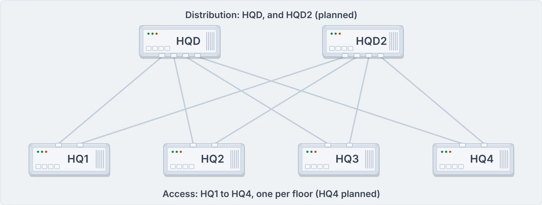
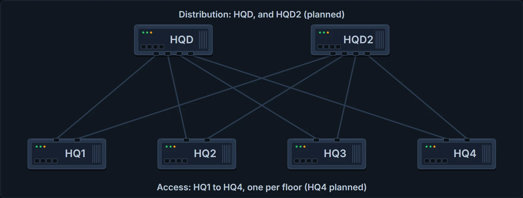
Ravi's plan: HQD and HQD2 above, HQ1 to HQ4 below, each floor switch linked to both. No floor switch links to another.
Two lines on a drawing aren't redundancy by themselves. The second uplink only helps if something lets it take over. Two links to the same distribution switch can work as one EtherChannel (03.2.1); links to two different switches rely on spanning tree unblocking the spare (03.3.1), or on routing choosing the other path. And HQD2 alone isn't the whole answer: R3's trunk, PAY1 and WLC1 hang off HQD only, so they would need a path through HQD2 as well. Ravi notes that for later.
Star, mesh, hybrid
A few words describe how switches are linked. A star: one central device linked to several others, like an access switch and its desk cables, drawn radiating out. A full mesh: a link between every pair of devices. A partial mesh: links between some pairs, but not all. Any group of devices with more links than a star is some kind of mesh.
A hybrid is a design combining those ideas, and that is what a two-tier campus is.
Why not simply link every switch to every other one, so any failure has a way round? Count first.
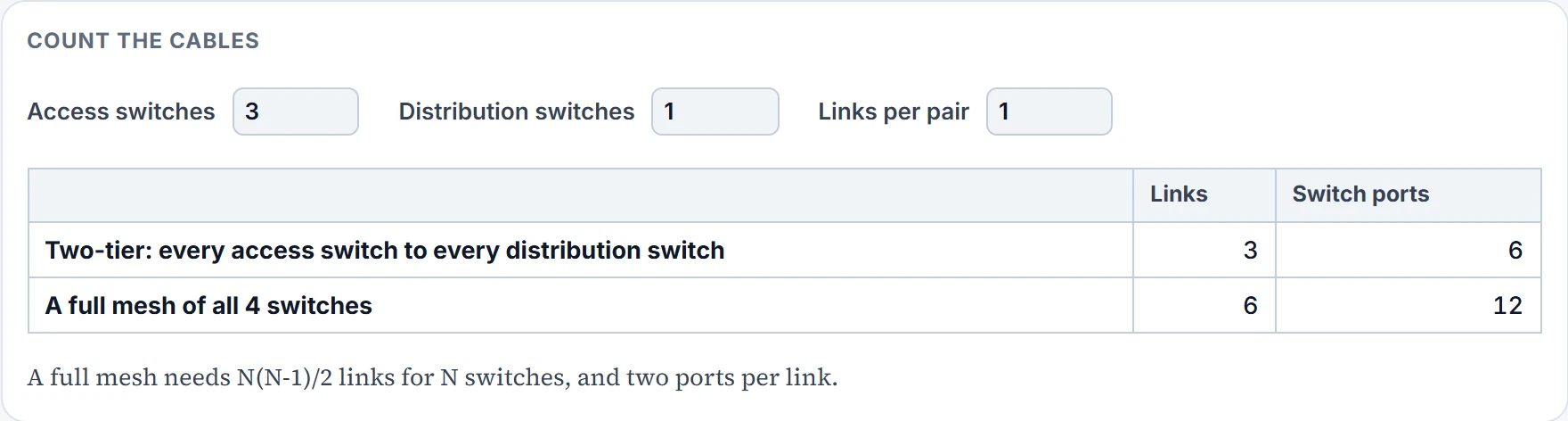
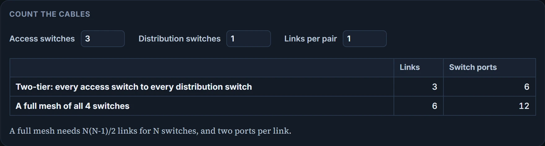
A full mesh of N switches needs N(N-1)/2 links and two ports for each. Six switches: 15 links, 30 ports. A large campus might have about 1000 PCs on 40 access switches, around 25 user ports each plus uplinks, with gigabit user ports and uplinks, and 2 distribution switches joined by faster links (a pair of 10 Gbps, say), which also connect the routers that lead to the WAN. A full mesh of all 42 switches would take 861 links and 1722 ports; two links from every access switch to each distribution switch take 160 uplinks and 320 ports. The two-tier design is a star at each access switch plus a partial mesh of uplinks, and it scales because, by design, access switches don't link to each other.
Everyone cabled to everyone turns the wiring closet into spaghetti with labels.
Continue the lesson
The whole lesson, with its drawings and its questions. 2 more sections after the ones above.