
Software-Defined Networking: Underlay, Overlay and Fabric
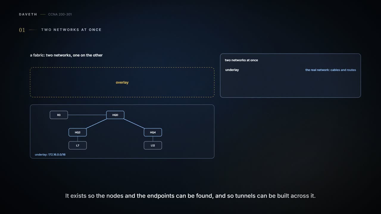
A campus fabric is two networks laid one on the other. The underlay is the physical network and the routing that gives every node a route to every other. The overlay is built on top: an edge node puts a user's whole frame inside VXLAN, UDP and an outer IP header, tunnels it across the underlay, and the far edge takes the wrapping off.
By Arif, founder of Daveth · Updated
The full 12 min walkthrough is in Daveth Pro (Network). See what the plan opens
What this page answers
What is an overlay network?
A network built on top of another: in a campus fabric, edge nodes tunnel users' frames across the physical network, the underlay, inside new headers, so the users' addresses travel untouched between edges. Read it in “Two networks at once”
What is the difference between an underlay and an overlay?
The underlay is the physical switches, routers and links, and the routing that lets every fabric node reach every other. The overlay is the tunnels between edge nodes that carry the users' traffic over it. Read it in “The underlay: routed from edge to edge”
Two networks at once
Month ten, still. Before any controller arrives (10.1), Ravi wants to know what it would build. Its campus design is called a fabric, and the word covers two networks laid one on the other.
The underlay is the physical network: the switches, routers, cables and wireless links, and the routing that gives every node in the fabric an IP route to every other, so the nodes and endpoints can be discovered and the tunnels built. The overlay is a set of tunnels between the fabric's switches, carrying the users' traffic from one side of the fabric to the other. The fabric is the two together. In controller terms (10.1), all of it sits south of the controller. Here is the underlay, as Ravi's plan would build it, with its own addresses from 172.16.0.0/16, a space the users never see:
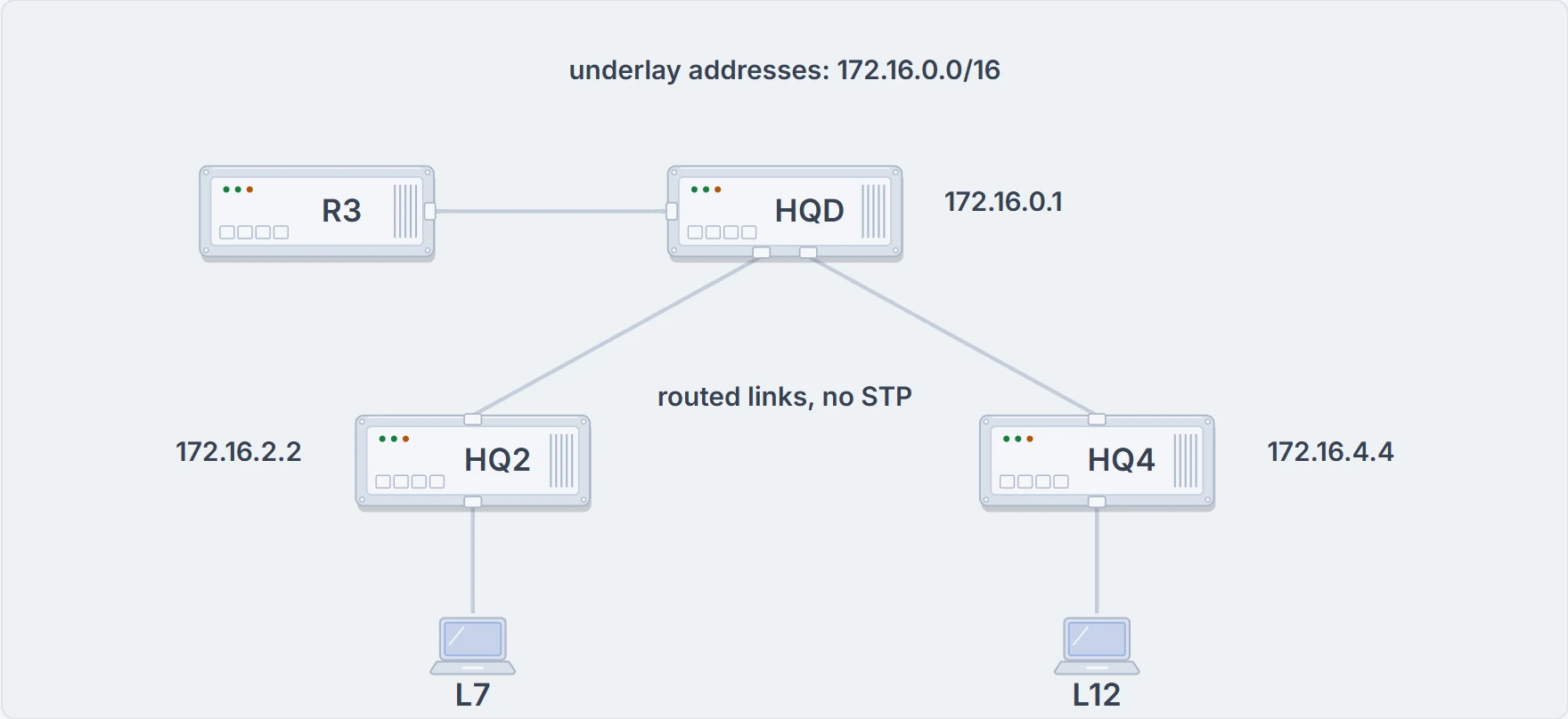
The underlay: the fabric's switches and the routed links between them, each switch with its own underlay address. R3, beyond HQD, is outside the fabric.
And here is the overlay. It leaves almost everything out. Only the two edge nodes appear (the fabric's name for the switches endpoints plug into), joined by a tunnel:
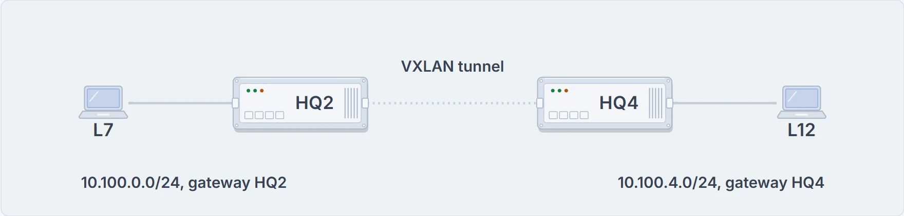
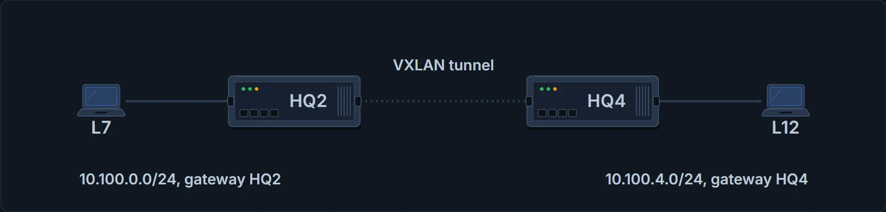
The overlay: just the two edge nodes, the tunnel between them, and the users.
No. The underlay's routing tables hold only underlay addresses, and they route only between the fabric's nodes. L7's and L12's addresses belong to the overlay: they travel inside the tunnels, where HQD, routing the underlay, never needs to look.
The roads carry sealed tubes. The note inside has a different address from the label on the tube.
The underlay: routed from edge to edge
A fabric can be built on the switches already installed, next to the traffic they carry today, or on new ones. Roles come first: which switch will be an edge, border or control node decides the hardware and software it needs. On existing switches, the hardware and software must be on the supported list for the role each will play, and the controller shouldn't be let loose on an underlay that production traffic depends on: people configure that part. With new switches, the controller can configure the underlay itself, with the same consistent settings everywhere, and endpoints can be moved across to the fabric over time. Either way, the ordinary campus questions still apply: how many ports, at what speeds, stacks or not, the cabling already in place, PoE and its budget (09.5), and the capacity of the links between switches.
Each switch has a role. Edge nodes connect endpoints, as access switches do; here, HQ2 and HQ4. A border node connects the fabric to what is outside it, such as the WAN routers. A control node runs the fabric's control plane, the map server that appears below, and needs more CPU and memory. In Ravi's plan HQD is both, with R3 beyond it.
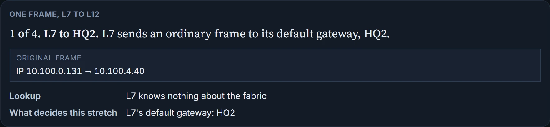
A traditional access layer is Layer 2: each access switch has two uplinks to the distribution switches, STP blocks one of them, and the distribution switches share the default gateway with an FHRP such as HSRP. A fabric doesn't have to follow those rules. With new switches, the controller builds a routed access underlay instead, a design that existed long before fabrics, but suits their tunnels well. Every switch is a Layer 3 switch, running the IS-IS routing protocol. Every link between switches, EtherChannels included, is a routed link, so STP isn't needed; the routing protocol picks the paths. And the edge node is the endpoints' default gateway, so no FHRP is needed either. In Ravi's plan that means a subnet per edge node: L7 stays in 10.100.0.0/24 on HQ2, and the fourth floor gets 10.100.4.0/24 on HQ4, where L12 sits.
The overlay: a frame inside a packet
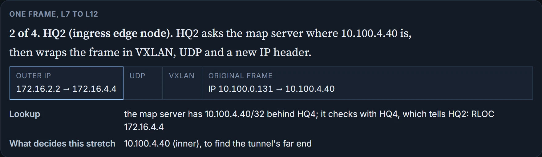
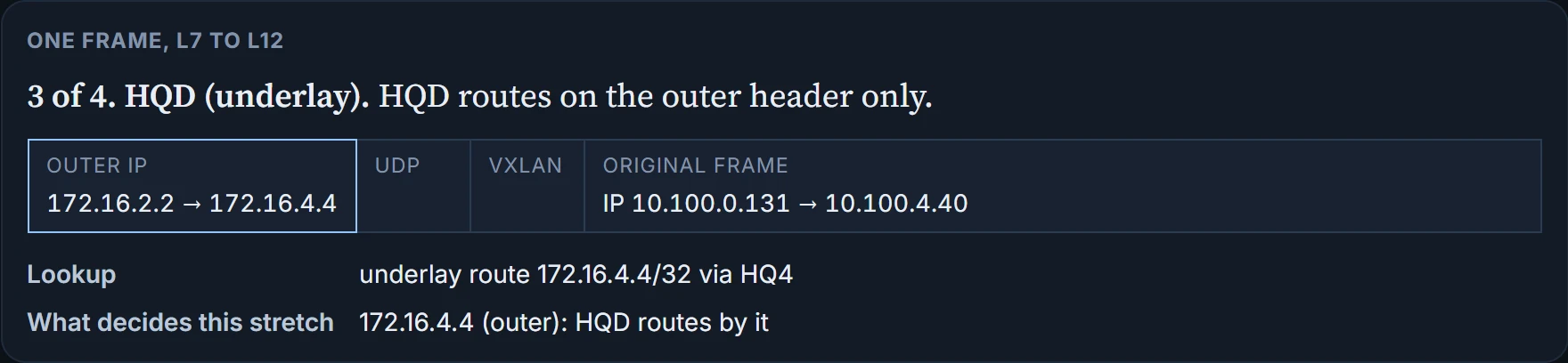
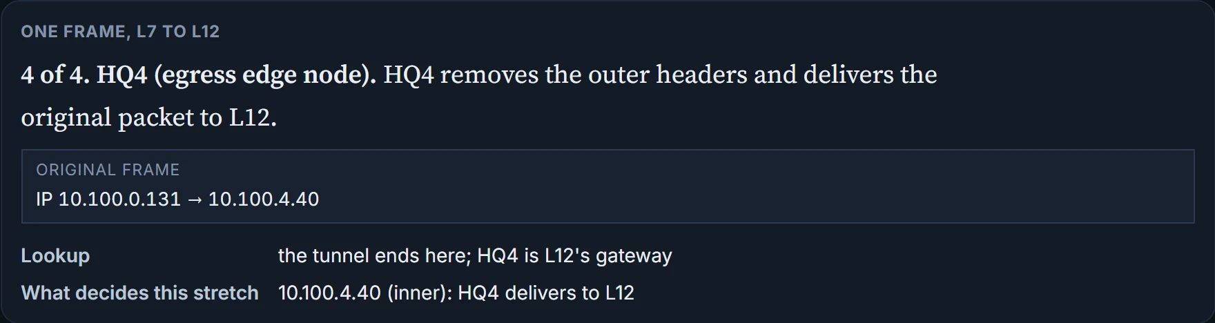
172.16.4.4. HQ2, the ingress node (in LISP's terms, the ingress tunnel router), puts L7's whole frame inside new headers: a VXLAN header, then UDP, then an outer IP header from HQ2's underlay address to HQ4's. HQD routes on that outer header like any other packet. L12's address travels inside, untouched, until HQ4 takes the wrapping off and delivers the original packet to L12. But HQ2 had to know that 172.16.4.4 was the right far end.
It asks. Edge nodes learn their own endpoints the usual ways, by MAC address, IP address and subnet, and register each one with the fabric's map server: this endpoint identifier (EID) can be reached through this routing locator (RLOC), the edge node's underlay address. When HQ2 gets a frame for a destination it hasn't sent to before, it asks the map server where 10.100.4.40 is. The map server finds the entry HQ4 registered and checks with HQ4, and HQ4 tells HQ2: behind 172.16.4.4. HQ2 then tunnels the frame to HQ4.
The protocol behind the map server is LISP. The idea matters more than the name: for the users' traffic, the fabric's control plane is a lookup service. The edge nodes don't learn each other's endpoints the traditional ways, from the source MAC addresses of frames or from a routing protocol run between them.
Now the whole trip, one stretch at a time:
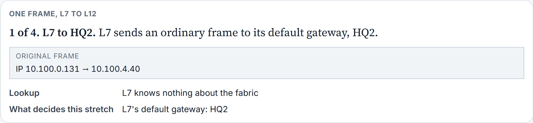
Step 1 of 4
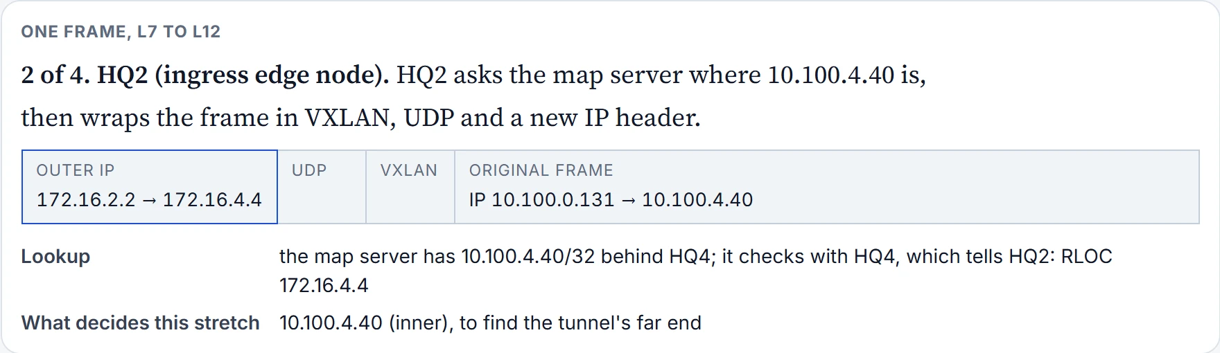
Step 2 of 4
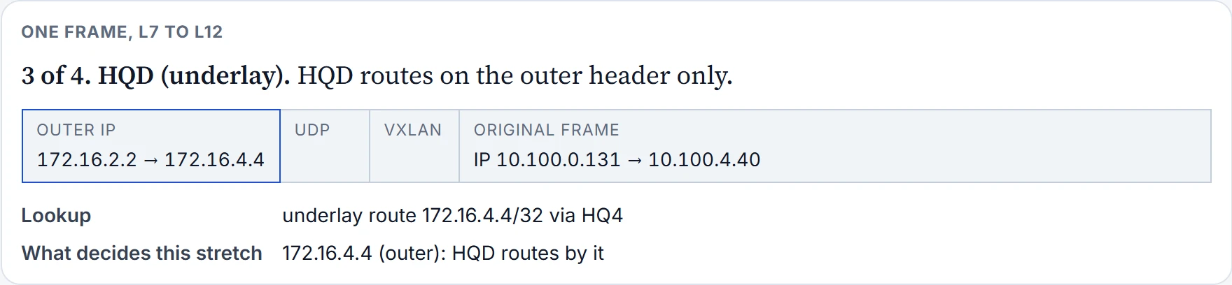
Step 3 of 4
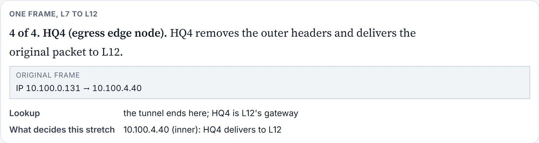
Step 4 of 4
The tunnelling method here is VXLAN (Virtual Extensible LAN), chosen for three reasons. Each switch's ASIC (10.1) does the wrapping and unwrapping, so there's no performance cost; it is also why a switch must be on the supported list: its ASIC has to be able to do it. Its header has room for the extra fields a fabric needs. And it carries the whole data-link frame, not just the IP packet, so the fabric can offer Layer 2 forwarding as well as Layer 3. (This trip is routed, between two subnets; carrying the whole frame is what also allows the Layer 2 kind.) VXLAN is one way to build an overlay, the one this design uses; it isn't the only one.
Continue the lesson
The whole lesson, with its drawings and its questions. The rest of this section and 2 more after it.