
Traffic capture
SPAN copies received, sent or both traffic from source ports or VLANs to a destination port for analysis: a session is two lines, what to copy and where to send it. RSPAN carries the copies between switches in a reserved VLAN that only travels on trunks, so it stops at a routed hop. On-board packet capture hands packets to the switch's own CPU instead, which costs it work.
By Arif, founder of Daveth · Updated
The full 7 min walkthrough is in Daveth Pro (Network). See what the plan opens
What this page answers
What is the difference between SPAN and RSPAN?
Local SPAN keeps sources and destination on one switch. RSPAN puts them on different switches and carries the copies in a reserved VLAN, which only flows on trunk ports. Read it in “Across a routed hop”
Can RSPAN cross a router?
Not by this course's reading: the RSPAN VLAN only travels on trunks, and a routed hop has no trunk to carry it. Read it in “Across a routed hop”
Does Embedded Packet Capture affect the switch?
It copies packets to the CPU, which normal hardware forwarding never troubles, so it adds load the switch did not have before. Read it in “A copy to the CPU”
A copy out of another port
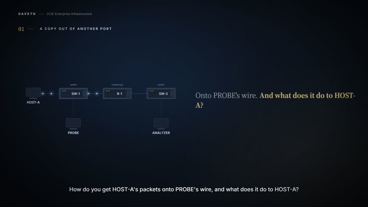
HOST-A is on SW-1's Gi1/0/1, and PROBE is on Gi1/0/2 of the same switch. How do you get HOST-A's packets onto PROBE's wire, and what does it do to HOST-A?
SPAN copies traffic (received, sent, or both) from source ports or source VLANs to a destination port, so it can be analysed. Local SPAN keeps the whole thing inside one switch: sources and destination are all on the same box.
A session is two lines: what to copy, and where to send it. Name a direction or you get both, because leaving it out means sent and received.
Configuration: local SPAN session 1, on this network, with this scenario's ports, addresses and names.
SW-1# configure terminal
SW-1(config)# monitor session 1 source interface gigabitethernet1/0/1
SW-1(config)# monitor session 1 destination interface gigabitethernet1/0/2 encapsulation replicate
SW-1(config)# end
Proves: The session on SW-1 proves which port SW-1 copies and which port the copy leaves by. Does not prove: that the copy fits the destination port, or that PROBE is reading it.
And what does it do to the traffic being copied? Nothing. Mirroring does not affect how the source port or VLAN switches its own traffic: a point worth holding on to, because the next reading looks like a contradiction.
Computed from the state: the copy with 4 Mb/s received and 3 Mb/s sent. No command prints it.
source Gi1/0/1 switching      unaffected
copy onto Gi1/0/2             7 Mb/s
PROBE port speed              10 Mb/s
copies dropped                no
Now HOST-A starts a restore and sends 8 Mb/s. The copy carries both directions. What happens on a 10 Mb/s port?
Every monitored packet is sent twice: once as ordinary traffic, once as a copy. So a destination port has to carry the sum of everything it is mirroring, and an oversubscribed one drops the excess: a 10 Mb/s port watching a 100 Mb/s port is the standard way to lose packets you were trying to look at.
Computed from the state: the copy with 4 Mb/s received and 8 Mb/s sent. No command prints it.
source Gi1/0/1 switching      unaffected
copy onto Gi1/0/2             12 Mb/s
PROBE port speed              10 Mb/s
copies dropped                yes
Look at the first row and the last. The source is still switched as before; the copies are what get dropped, so PROBE sees a gap that HOST-A's users never had. The impact lands on the evidence, not the service.
And the destination port carries nothing else. Only monitored traffic passes through it, which is why you do not put a working host on one and expect it to keep working.
Across a routed hop
ANALYZER is on SW-2, and R-1 routes between the two switches. There is no Layer 2 path. Which mirror can reach it?
RSPAN puts the sources and the destination on different switches, and carries the copies between them in a VLAN reserved for the purpose. That VLAN is the whole mechanism, and it only flows on trunk ports.
By this course's reading, RSPAN stops at R-1. A routed hop has no trunk to offer, and a VLAN that only travels on trunks has nowhere to go. That conclusion is ours, drawn from the trunk rule rather than stated anywhere as a rule of its own. RSPAN also never carries BPDUs or the other Layer 2 protocols, which matters the day you try to use it to chase a spanning-tree problem.
ERSPAN is the one that crosses a routed network. It wraps the copies in GRE and routes them, which is why it has three parts rather than two: a source session, the encapsulated traffic in flight, and a destination session at the far end. Miss the third and nothing arrives, with no error to tell you.
The two ends are tied together by an id. The same ERSPAN id has to be configured in the source session and in the destination session, or the far end will not recognise what reaches it.
Configuration: the ERSPAN source session, on this network, with this scenario's ports, addresses and names.
SW-1# configure terminal
SW-1(config)# monitor session 2 type erspan-source
SW-1(config-mon-erspan-src)# source interface GigabitEthernet1/0/1 rx
SW-1(config-mon-erspan-src)# destination
SW-1(config-mon-erspan-src-dst)# erspan-id 100
SW-1(config-mon-erspan-src-dst)# ip address 10.0.0.2
SW-1(config-mon-erspan-src-dst)# origin ip address 10.0.0.1
SW-1(config-mon-erspan-src-dst)# exit
SW-1(config-mon-erspan-src)# no shutdown
SW-1(config-mon-erspan-src)# end
Proves: The session on SW-1 proves that SW-1 has an enabled ERSPAN source session with that ID and destination address. Does not prove: that SW-2 has a destination session, or that ANALYZER has received one packet.
What can SW-1 tell you about its own half? A source session's detail reads like this:
Example output: a source session's detail. The interfaces, addresses and counts in it belong to the example, not to this network; read it for its shape.
Device# show monitor session erspan-source detail
Type                     : ERSPAN Source Session
Status                   : Admin Enabled
Destination IP Address   : 192.0.2.1
Destination ERSPAN ID    : 251
Origin IP Address        : 10.10.10.216
ERSPAN header-type       : 3
Look at the Status row. Admin Enabled is about this session and nothing further along.
Proves: That output proves the source session's type, that it is enabled, and the ID and addresses it sends with. Does not prove: that any device holds a matching destination session. Nothing in it comes from the far end.
Computed from the state: the copy with no destination session on SW-2. No command prints it.
SW-1 source session       Admin Enabled
SW-2 destination session  none
copy on the routed links  4 Mb/s
ANALYZER receives         no
By this course's reading, ANALYZER receives nothing yet. Nothing in the session detail shows it: the source session reads enabled while the third of the three parts, the destination session, is missing.
So what does SW-2 need before ANALYZER sees a packet? A session of its own, with an address it owns.
The address in the source session has to be one the far switch actually owns, a local interface or a loopback on it, and the destination session has to name the same address. Point it at something SW-2 does not own and the copies are routed to nobody.
Configuration: the ERSPAN destination session, on this network, with this scenario's ports, addresses and names.
SW-2# configure terminal
SW-2(config)# monitor session 1 type erspan-destination
SW-2(config-mon-erspan-dst)# destination interface GigabitEthernet1/0/5
SW-2(config-mon-erspan-dst)# source
SW-2(config-mon-erspan-dst-src)# erspan-id 100
SW-2(config-mon-erspan-dst-src)# ip address 10.0.0.2
SW-2(config-mon-erspan-dst-src)# end
Computed from the state: the copy with both sessions. No command prints it.
SW-1 source session       Admin Enabled
SW-2 destination session  ID 100
copy on the routed links  4 Mb/s
ANALYZER receives         yes
Notice where the address points: at SW-2, not at ANALYZER. The destination session runs on a switch, and ANALYZER hangs off its destination interface.
And over IPv6? Both families carry it, delivery and transport headers exist for each, so the session changes by two lines, not by design:
Configuration: the two lines that differ when the same source session is built for IPv6, with this scenario's addresses; the rest of the session is as above. Whether one session carries an IPv4 and an IPv6 destination at once is not claimed.
SW-1# configure terminal
SW-1(config)# monitor session 2 type erspan-source
SW-1(config-mon-erspan-src)# destination
SW-1(config-mon-erspan-src-dst)# ipv6 address 2001:db8:0:1::2
SW-1(config-mon-erspan-src-dst)# origin ipv6 address 2001:db8:0:1::1
SW-1(config-mon-erspan-src-dst)# end
How many source sessions has SW-1 used now? Count them against the limit. Local SPAN, RSPAN and ERSPAN all spend from the same allowance of source sessions, and a switch has far fewer of those than of sessions overall.
Computed from the state: source sessions in use. No command prints it.
SW-1 source sessions 2 of 8
And traffic on a source port that is already ERSPAN? A source session does not copy traffic that is itself ERSPAN-encapsulated, so mirroring a mirror gets you nothing. The header is the Type-II form unless you ask for another.
A copy to the CPU
No port, no second switch: SW-1 keeps the packets itself. Where does that copy go, and who pays for it?
On-board packet capture takes packets flowing to, through and from the switch and hands them to the CPU. That is the cost, and it is the whole cost: forwarding normally happens in hardware and never troubles the processor, so copying packets up to it is a load the switch did not have before.
So this is not a free observation; it is work the switch was not otherwise doing. Asking for everything is the fastest way to find that out, because the volume arrives at the one part of the switch that forwards nothing, and the file grows at the same rate.
A capture point names where to tap and which way, and takes limits: how long to run for, how many packets, how much of each packet to keep.
How do you read back what a capture point was given? Ask it for its parameters, and it prints them as the commands that would create it:
Example output: a capture point's parameters, read back. The interfaces, addresses and counts in it belong to the example, not to this network; read it for its shape.
Device# show monitor capture mycap parameter
   monitor capture mycap interface GigabitEthernet1/0/1 in
   monitor capture mycap match ipv4  any any
   monitor capture mycap limit duration 60 packet-len 400
Configuration: capture point mycap, on this network, with this scenario's ports, addresses and names.
SW-1# monitor capture mycap interface GigabitEthernet1/0/1 in
SW-1# monitor capture mycap match any
SW-1# monitor capture mycap limit duration 60
SW-1# monitor capture mycap start
Proves: The capture configuration on SW-1 proves what the capture point is attached to, what it matches and its limit. Does not prove: how many packets reached the CPU, or what that did to it.
Computed from the state: what mycap delivers. No command prints it.
capture points defined    1 of 8
active                    mycap, 1 port
offered                   600 pps
copied to the CPU         600 pps
policed to 1000 pps       yes
Notice that Gi1/0/1 is also local SPAN's source. That combination is allowed: capture can tap a port that is a SPAN source, certainly on the way in and possibly on the way out. The other end is refused: you cannot capture on a SPAN destination port, which is the one people reach for first because it looks like where the interesting traffic is.
Continue the lesson
The whole lesson, with its drawings and its questions. 4 more sections after the ones above.